Page 1 of 1
Wiring diodes this way possible?
Posted: 11 Aug 2015, 10:57
by Eszett
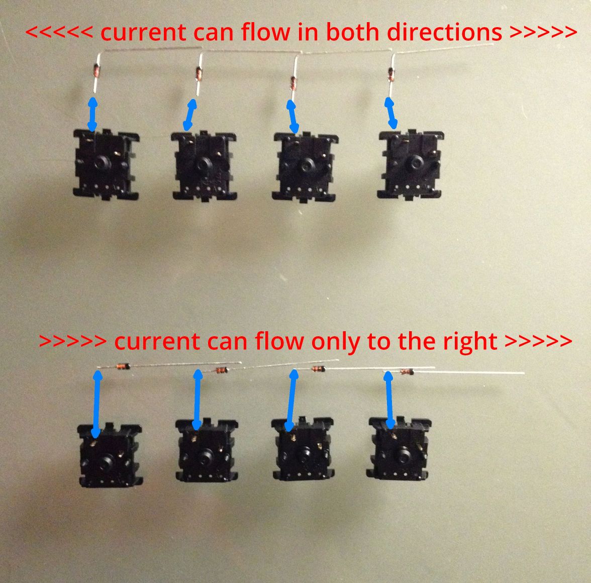
Hi! Usually rows are wired with diodes like the upper part of my photo shows. But will it work when I wire them as shown below, too?

- IMG_0171.JPG (181.75 KiB) Viewed 2247 times
Posted: 11 Aug 2015, 12:00
by Muirium
Nope. They must be in parallel. Your second picture is electrically equivalent to just one diode.
Posted: 11 Aug 2015, 12:10
by Eszett
Hi Muirium! I had a bad gut feeling

Posted: 11 Aug 2015, 13:21
by Muirium
What's your motive for wanting to wire them up a different way?
I need to tear down my first hand-wired keyboard's insides and do the matrix over, so I can finally rid the board of a ghost my early handiwork trapped inside! I know a bit better now about how important it is to keep things tight and orderly. But then I am a sloppy worker…
Posted: 11 Aug 2015, 20:15
by Eszett
Hi Muirium! There is no motive, I made an error in reasoning, forgetting about the elementary electronic principles I once learned in school. Lucky that I did not solder this.
Posted: 12 Aug 2015, 02:59
by jacobolus
Muirium isn’t quite right here. A bunch of diodes in series with a branch toward each switch is definitely *not* the same as just one diode.
There’s still a problem though, which is that if you have diodes in series, you get a voltage drop across each one.
The way you should think of your keyboard matrix is: you’re making a grid of rows and columns, where each intersection between a row and a column is blocked by a switch. The goal is to make sure that even when multiple switches are pressed, current is only flowing in one direction through each switch itself, so there’s never any confusion about precisely which switches are pressed.
So what you want is to build a bunch of little gadgets each made of a switch plus a diode in series, and then stick one of those gadgets at each row/column intersection.
Each “row” and each “column” you can just think of as being anything that is directly connected by wire to a particular input or output pin. In practice people sometimes solder the legs of the diodes to each other as a way of connecting one side of each of those diodes to the same microcontroller pin, but if you wanted you could have a separate little wire connecting each diode to the appropriate I/O pin.
Posted: 12 Aug 2015, 17:15
by Findecanor
You could get ghost keys with that wiring, but only from the left to the right.
Posted: 17 Aug 2015, 17:56
by hrvoje
Standard diodes have a voltage drop of around 0.6 V. If bunch of them would be wired in series like that, it would soon fall below the threshold where the circuit detects a logical 1...