Page 1 of 4
Modeling an F key mechanism
Posted: 12 May 2023, 04:32
by DMA
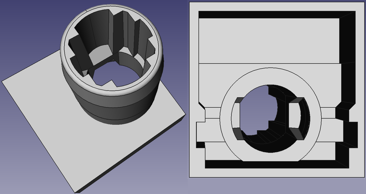
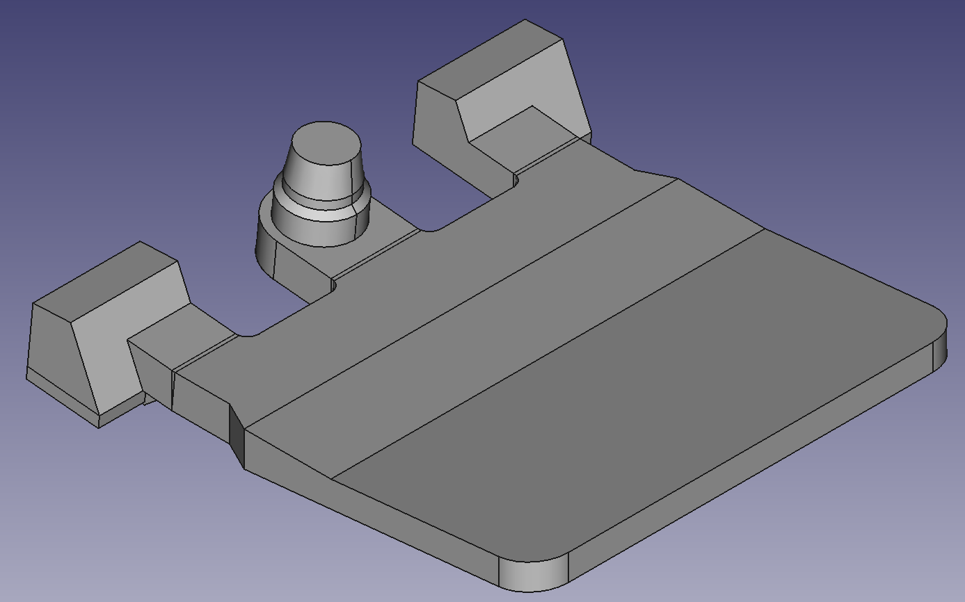
So, with heaps of free time, I embarked on modelling model F key assembly in FreeCAD.
- f-barrel.png (63.7 KiB) Viewed 62647 times
- f-flipper-isometric.png (41.46 KiB) Viewed 62647 times
- f-stem.png (71.93 KiB) Viewed 62647 times
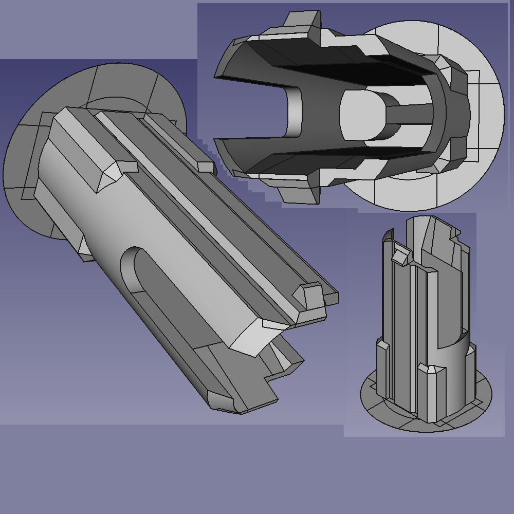
And let me tell you, model F mold makers were showing off. A LOT. Parting lines in _really_ weird places (they mostly make sense, but, like, **weird**), _huge_ chamfers inside the barrel (different lengths, too!), complete lack of taper anywhere inside the barrel or on outsides of the stem (the force to push the part off the mold must have been HUGE!), seemingly 3-part mold for the stem (key outer shape, key inner shape + stem outer shape, stem inner shape) with key needing to flex when pushed off the inner key shape (it flexes every time you pull it from the keyboard anyway - but when it's pushed off the mold it's still hot!), round edges, square edges, fancy chamfers..
But IBM outdid itself on the flipper.
- f-flipper.png (42.2 KiB) Viewed 62647 times
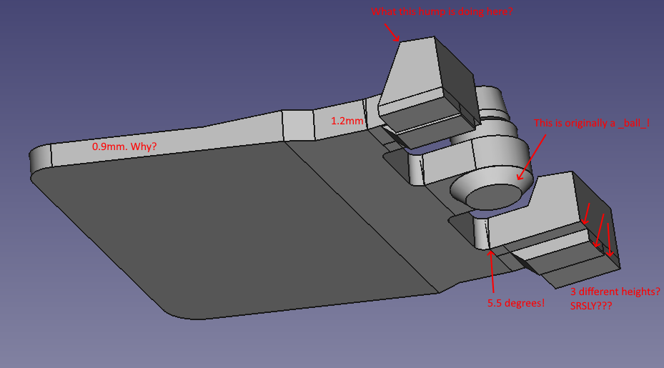
The flipper is strangely baroque: One can easily notice it's bent once - but really it's bent _twice_. The first bend is easy 1:10 slope. Sure, it's joined in a weird way by the thicker middle plate, but e-z, no worries. But then the supporting part - legs and the spring holder - are also bent up, 5.5 degrees. No more, no less. Why wouldn't they be content with just a single bend? It's certainly doable. And the pivot point for that bend is in a kinda weird place, too - not on the cutout line, but where the rounded parts of the cutout end.
Then the legs themselves. The bottom part has 3(!) different heights! M kinda fixed that by extending the "ski" up to the edges - but they still kept the middle cutout for some reason. Were they worried about material use? Weight? Aesthetics? Or were they just flexing?
Also this bump on top of the leg. It has a weird slope which makes no sense. Yeah, it's parallel to the ground when the flipper is down, and it seems to be ~2.75mm in height (which is about the height of the flipper cavity), and when the flipper is up it's top is ~2.75mm from the ground too - but why molding it that way, when the spring is firmly pressing on the flipper from above at rest? M just has constant 3.4mm height of the flipper cavity and it's totally fine, after all. What is it? Belt-and-suspenders?
Then there's this ball under the spring holder which floats full 0.1mm above the ground plane, so it doesn't even touch anything. Is it there to limit holder's deformation if somebody presses on the spring too firmly? It doesn't have to be a ball - flipper pivots way forward of spring holder, holder just lifts off vertically, even it was a cylinder nobody would care..
But yeah, I found a lot of interesting details on the stem. Like key stabilizers on the top increasing stabilization while key goes down plus stem itself stabilizing at the bottom by the ring (there's visible effort to minimize the contact area so the key doesn't bind!). Or the spring guides on the sides of the spring holder.
Those with sharper eyes may notice that the barrel base is square and enclosed. Yeah, if I ever shamble to production with this - those will be 19x19mm buckling spring modules with LEDs and MX mount (and couple other things like flipping to the side instead of down). Designed for flat 1.5mm plate, so that COTS plate stabilizers can be reused. Hopefully, they'll support 5mm key travel

Re: Modeling an F key mechanism
Posted: 13 May 2023, 01:26
by AndyJ
It would be interesting to compare those to the "New Model F" parts.
Re: Modeling an F key mechanism
Posted: 13 May 2023, 05:28
by DMA
AndyJ wrote: ↑13 May 2023, 01:26
It would be interesting to compare those to the "New Model F" parts.
From
download/file.php?id=24323 - flippers look OK-ish, but barrels.. my god, those are real ugly and shoddy AF.
Re: Modeling an F key mechanism
Posted: 13 May 2023, 21:35
by vyquad
i think this could work just fine 3d printed if theres post processing done
Re: Modeling an F key mechanism
Posted: 14 May 2023, 22:45
by DMA
I found a place for a pretty huge LED (like, 3528 will fit with a lot of space to spare) without sacrificing stem compatibility.
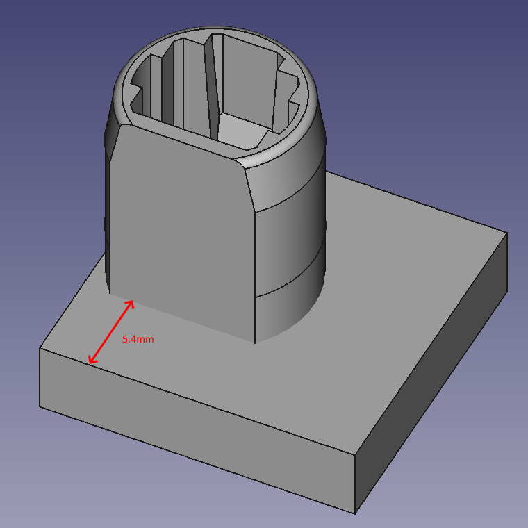
- f-barrel-isometric.png (29.3 KiB) Viewed 62435 times
Also, flipper will have to be shortened by ~2mm, although there's still a trick up my sleeve to reuse 2mm of space at the back of the key, beyond the pivot point of the flipper.
For lulz and shine, I'll try to make the barrels from polycarbonate.
Of course, due to LED-lighted keys flipping to the left and being MX-mount (or ALPS, doesn't matter - although my understanding is MX keycaps have a lot more variety to them), original keys will have to have a different plate: cutouts rotated 90 degrees CCW and more key cutouts for F-style stabilizers. PCB will have to be different, too - but if you want to reuse your F keys - flat or curved - it's doable.
Re: Modeling an F key mechanism
Posted: 15 May 2023, 02:15
by DMA
Accurate model allows for more than just reproduction. It allows to look inside with precision not really achievable at home otherwise.
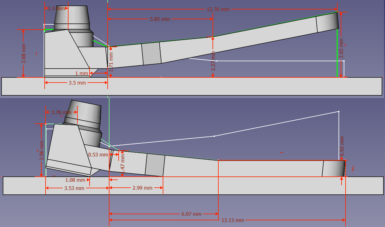
- f-flipper-up-down.png (62.76 KiB) Viewed 62413 times
Here's flipper at rest and pressed down. It's clearly visible that whole 4mm from the pivot point can be freely used for routing, because flipper doesn't touch the PCB there.
Re: Modeling an F key mechanism
Posted: 15 May 2023, 14:29
by Muirium
Okay, now I see what you’re up to. Or so I think.
I’d be wary about that little channel, though. Tolerances are real. You know how jiggly these flippers can be when inside a keyboard. There’s quite a bit of rotational play on show in every opened F.
Re: Modeling an F key mechanism
Posted: 15 May 2023, 16:06
by DMA
Muirium wrote: ↑15 May 2023, 14:29
Okay,
now I see what you’re up to. Or so I think.
I’d be wary about that little channel, though. Tolerances are real. You know how jiggly these flippers can be when inside a keyboard. There’s quite a bit of rotational play on show in every opened F.
It can't be too jiggly. It just looks that way due to huge 0.5mm clearance between barrel and flipper. The worrying part, tolerance-wise, is the upper stabilizers (you need to look into keycap to even see them). There is a proof that tolerances aren't too tight - Ellipse's barrels, judging from the photos, are _really_ shoddy quality, and yet they work OK.
Re: Modeling an F key mechanism
Posted: 16 May 2023, 00:23
by DMA
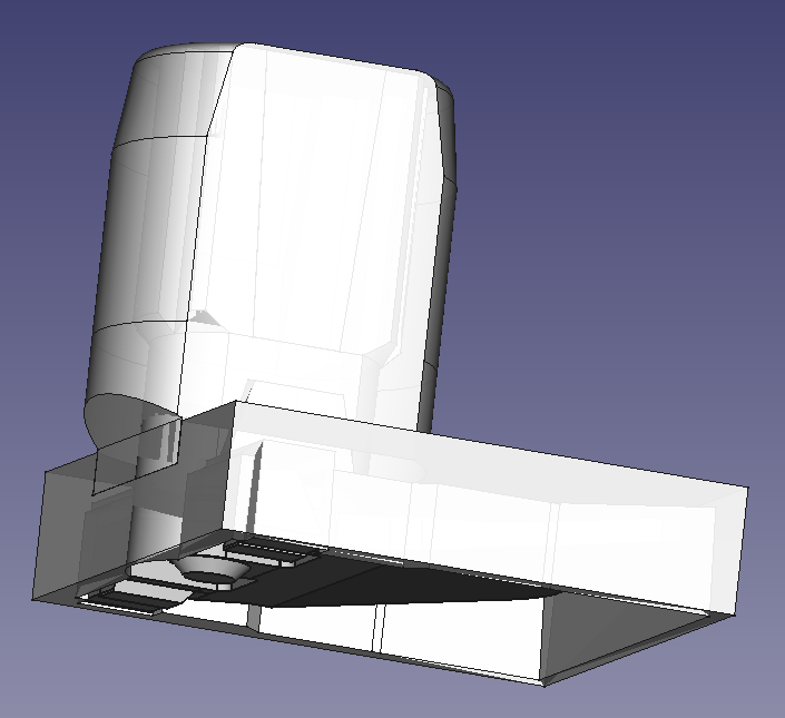
- f-barrel-shifted.png (52.19 KiB) Viewed 62332 times
Actually, one can just shift the barrel 1.8mm to the side, and everything will fit into 19x19mm module. Yeah, sure, it looks a bit weird - but it won't be visible when assembled.
That 30 degree cut is there not to lose the bent plate compatibility. Although, now that I remembered that bent plate needs 21mm row height, it could just be a straight cut.

Re: Modeling an F key mechanism
Posted: 17 May 2023, 01:51
by DMA
I figured out why unicomp keys are so bitchy about placement. Some surgery was involved (don't worry, it's the worst quality unicomp key from my collection - I can't bring myself to destroying a single-piece one.)
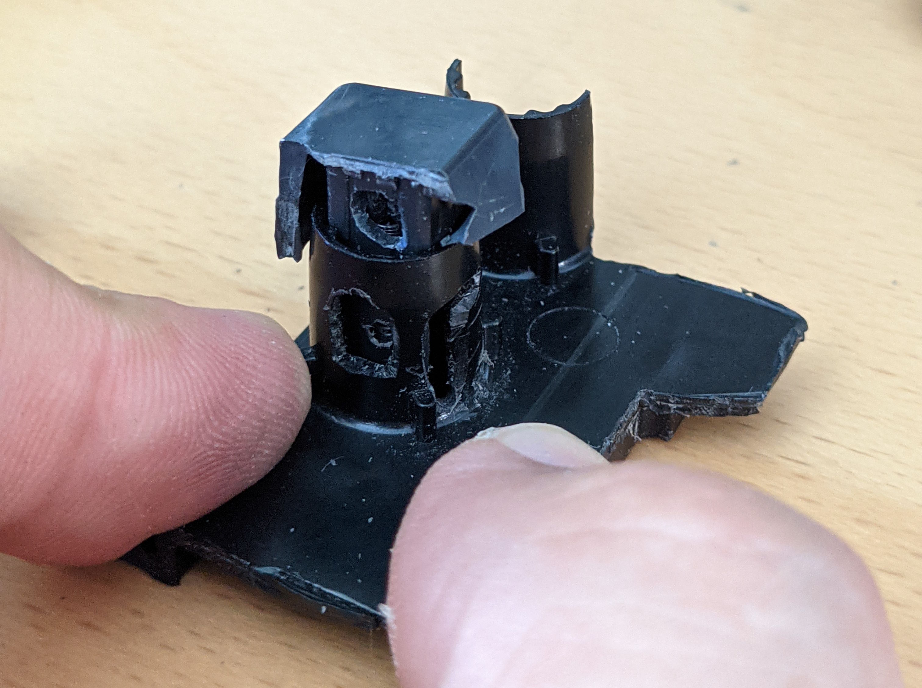
- a_key_with_a_view.jpg (718.52 KiB) Viewed 62237 times
The root cause is a spring not seating properly: instead of being tilted to 13 degrees by the sloped plate (green outline) it sits almost vertically (red outline), and the magic of "catastrophic spring buckling" doesn't happen without that additional nudge.
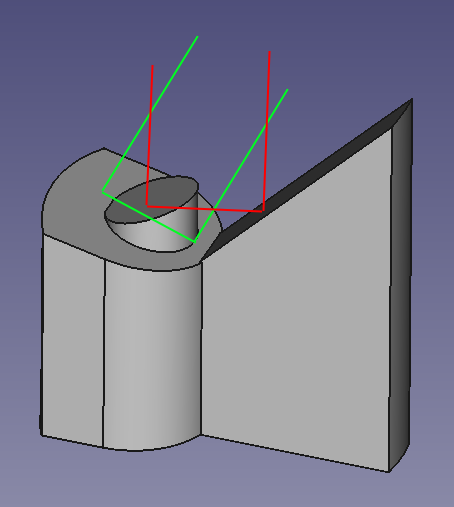
- wrong-spring.png (19.19 KiB) Viewed 62237 times
Turns out, that small nub on the spring stand is there not to prevent the spring from curling - it's there to nudge the spring onto the sloped plate: the key on the photo has that nub completely removed and yet, if you manage to set spring up in a correct manner, everything works perfectly fine.
That nub's shape is pretty complex - what you see on the model is wrong. I'll try to fix the issue once and for all - seems doable.
Re: Modeling an F key mechanism
Posted: 18 May 2023, 06:23
by DMA
Wasn't easy, but here it is - 19x19mm, MX-mount, LED-enabled, original stem- and flipper-compatible buckling spring assembly, free of that pesky "spring doesn't buckle and requires reseating" bug.
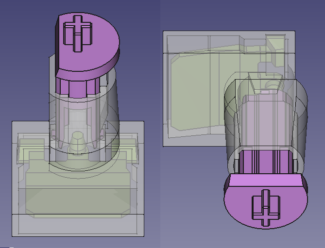
- f-assembly-final.png (42 KiB) Viewed 62145 times
Re: Modeling an F key mechanism
Posted: 18 May 2023, 07:42
by kbdfr
DMA wrote: ↑18 May 2023, 06:23
Wasn't easy, but here it is - 19x19mm, MX-mount […] buckling spring assembly […].
While I am not familiar with IBM (and even less with the kind of amazing work you're doing here), it seems to me that there would be a problem with MX keycaps because they have a specific profile for each row while IBM keycaps all have the same profile.
So if a keyboard with a bent plate and these assemblies were to be populated with MX keycaps, wouldn't the rows then have a "double slope"?
And could this effect be annihilated by designing MX-mount sliders sliders with a different profile for each row?
Or is your buckling spring assembly not intended for (repairing) existing Model F keyboards, but also for keyboards without a bent plate?
Anyway, don't think your work goes unnoticed just because there are not many answers here

Re: Modeling an F key mechanism
Posted: 18 May 2023, 11:49
by Muirium
Fair point. I think he’s up to an entirely custom, flat backplate project which therefore really needs Cherry profiled keys. A lot of the complexity with making custom buckling spring keyboards comes from that curve and the idea here is to wave it goodbye, seems to me.
Re: Modeling an F key mechanism
Posted: 18 May 2023, 18:09
by DMA
kbdfr wrote: ↑18 May 2023, 07:42
While I am not familiar with IBM (and even less with the kind of amazing work you're doing here), it seems to me that there would be a problem with MX keycaps because they have a specific profile for each row while IBM keycaps all have the same profile.
So if a keyboard with a bent plate and these assemblies were to be populated with MX keycaps, wouldn't the rows then have a "double slope"?
Nope.
Flat plate - MX stabilizers, barrel assemblies suitably sunk into the plate. It will look from outside like weird round-body MX switches, optionally with RGB LEDs on top of them.
Bent plate - IBM keycaps, IBM stabilizers. No difference from vanilla model F. No LEDs either, because nobody makes transclusent IBM keycaps (and nobody ever will).
kbdfr wrote: ↑18 May 2023, 07:42
Or is your buckling spring assembly not intended for (repairing) existing Model F keyboards, but also for keyboards without a bent plate?
Repairing vanilla Fs should theoretically be possible, but you may need to shave a bit of plastic from the bottom of the barrel so that barrel sticks out at a proper angle. However, the barrel is the most indestructible part of the key assembly, and I don't anticipate anybody ever needing that.
TBH, bent plate is a royal pain in the ass without any benefit, so it should go the way of the dodo. Ellipse just doesn't have the balls to risk the minor redesign required.
Re: Modeling an F key mechanism
Posted: 18 May 2023, 18:22
by Ellipse
What about individual self-contained PCB solderable modules? That has been talked about in the past. They could either be capacitive (if the additional solder points would not affect the signal so much that it would be unusable) or regular metal contact with an updated flipper bottom (lower expected life in my view).
Regarding the new Model F barrels, please note that the earlier-linked photo showed the prototype barrels that were rejected. The mold was redone for the production units.
The barrel product page shows the production units which removed the issue with the flashing / excess plastic and the design issue discussed early on in the project:
https://www.modelfkeyboards.com/product/extra-barrel/
As a note the mold cavity number was removed from the location in that photo and relocated to the top side of the barrel to be more in line with the originals.
Re: Modeling an F key mechanism
Posted: 18 May 2023, 18:26
by Muirium
I am definitely in favour of contact based 'Model F modules', like Ellipse describes. Give them good contacts—not that membrane shit in Model M—and you've what could be an absolute barnstormer of a switch.
Re: Modeling an F key mechanism
Posted: 18 May 2023, 21:26
by DMA
Ellipse wrote: ↑18 May 2023, 18:22
What about individual self-contained PCB solderable modules?
_fuck_ no. There's simply no benefit. Capacitive sensing is not better than ohmic with diodes in any way - buckling spring is the benefit, but it needs space (mostly vertical tho), plus most people buy buckling spring for the _sound_, not _feel_, and the sound will be different - not better, not worse, just different, and that's a dead end.
This isn't about longevity either - nobody _really_ cares about expected life, it's all lip service.
Ellipse wrote: ↑18 May 2023, 18:22
Regarding the new Model F barrels, please note that the earlier-linked photo showed the prototype barrels that were rejected. The mold was redone for the production units.
Noted, but the text under photo clearly said "can you make the difference" - and I certainly can (although without spending a full week looking at the original barrels, I wouldn't be able to) Re:
https://www.modelfkeyboards.com/product/extra-barrel/ - the parting lines are still super-coarse - but this can actually help stabilize the stem without introducing too much binding. Also the surfaces are super-coarse, even where it matters - but hey, it apparently works, (at least I don't see hordes of people complaining about that).
Ellipse wrote: ↑18 May 2023, 18:22
As a note the mold cavity number was removed from the location in that photo and relocated to the top side of the barrel to be more in line with the originals.
Doesn't really matter - there's like 0.5mm gap between top of the flipper and bottom of the barrel.
Re: Modeling an F key mechanism
Posted: 18 May 2023, 21:35
by DMA
Muirium wrote: ↑18 May 2023, 18:26
I am definitely in favour of contact based 'Model F modules', like Ellipse describes. Give them good contacts—not that membrane shit in Model M—and you've what could be an absolute barnstormer of a switch.
I don't think so. First, the force that flipper generates is enough for the membrane shit but not for anything else. Second, it will be virtually silent, so nobody will buy it.
And third, instead of 3 molded components + spring it will be at least 7 + spring - which means it will be at least twice as expensive. It will also need that $300k assembly machine which killed the silo beam switch couple months ago.
The capacitive version will be even worse - those 15x15mm PCBs waste A LOT of PCB area for cuts, and take a lot of machine time for the cuts, so they will be, like, the most expensive PCBs in history, per unit of area.
Re: Modeling an F key mechanism
Posted: 23 May 2023, 07:28
by DMA
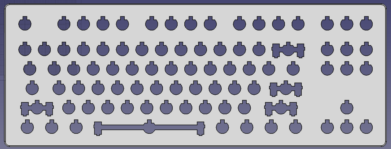
- tanks.png (23.15 KiB) Viewed 61819 times
LOL TANKS.
Stabilizers are actually a bit complicated - plate-mounted stabs are 5 mm deep, so those cuts will have to go thru the LED PCB and foam - which have to be thicc enough to keep those stabs away from the barrels.
But it's doable.
I know, I know, 2U stabs should have wider wire slots - but I don't want to make those wider than absolutely necessary (which is 4.6mm - 2U stab has the same legs as the space bar one, so it should fit).
Re: Modeling an F key mechanism
Posted: 23 May 2023, 23:21
by thefarside
Awesome project DMA! Regarding the plate, would it be possible to also have support for IBM AT and XT barrels? My only thinking there is using IBM barrels as future replacements.
Regarding the barrels and flippers, I’m curious what you think about having dampening options, similar to how alps added rubber bumpers to the slider. I’m not sure if a dampener or rubber materials could be used in the barrel or flipper, and if the dampening “ramps” from the model M flipper could be added to an F flipper, but it would be an interesting concept. I’ve always wondered about a silenced Model F for work, but wasn’t sure what could be changed without affecting the lightness and tactility.
Re: Modeling an F key mechanism
Posted: 24 May 2023, 00:27
by DMA
thefarside wrote: ↑23 May 2023, 23:21
Awesome project DMA! Regarding the plate, would it be possible to also have support for IBM AT and XT barrels? My only thinking there is using IBM barrels as future replacements.
Nope! IBM barrels are 19x20.8mm, which makes them a bit hard to put them onto a 19.05x19.05mm grid. It is, however, possible to put it onto a flat 19x21mm grid - which wcass did back in 2018: (
Idea and prototype,
final version disassembly). I helped with the controller for it - the second post contains some examples of my hand-soldering

thefarside wrote: ↑23 May 2023, 23:21
Regarding the barrels and flippers, I’m curious what you think about having dampening options, similar to how alps added rubber bumpers to the slider.
You mean like
viewtopic.php?f=7&t=16550 ? Yeah, it works on the upstroke.
Seriously though - nobody will ever buy a silent buckling spring. I can run an interest check - but I'm pretty sure it will be less than 10 people _worldwide_.
Also, as you can clearly see, this generated a lot of indignation in 2017

thefarside wrote: ↑23 May 2023, 23:21
I’m not sure if a dampener or rubber materials could be used in the barrel or flipper, and if the dampening “ramps” from the model M flipper could be added to an F flipper, but it would be an interesting concept. I’ve always wondered about a silenced Model F for work, but wasn’t sure what could be changed without affecting the lightness and tactility.
What dampening ramps? The only thing that keeps model M quieter is that membrane-pressing nub in the middle - by greatly reducing the flipper flight distance. I know, because I recently filed it off in the name of !!SCIENCE!! and, well,
it actually becomes louder than model F - likely because less inertial shorter flipper resulting in higher PCB impact speed.
Seriously though, I don't think making a completely silent capacitive buckling spring is possible (Mostly due to the fact that the flipper, when down, must be EXTREMELY close to the PCB - even a tiniest bread crumb under the flipper completely ruins the readout).
It can probably be made quiet enough by suspending the "barrels + sense card" assembly between two layers of foam and having heavy enough top and bottom plates. I haven't yet modeled that part, so can't show anything right now - you have to use your imagination.
Making a hole for a shock absorber in the barrel's "box" (and installing it) will further help with the key-up noise.
But it all circles back to this being a pretty expensive experiment, which I, as an unemployed person, cannot afford.
Re: Modeling an F key mechanism
Posted: 25 May 2023, 00:05
by DMA
So, I disassembled my F"SSK" and put random 2.5mm closed-cell polyethylene packing foam under the PCB like this
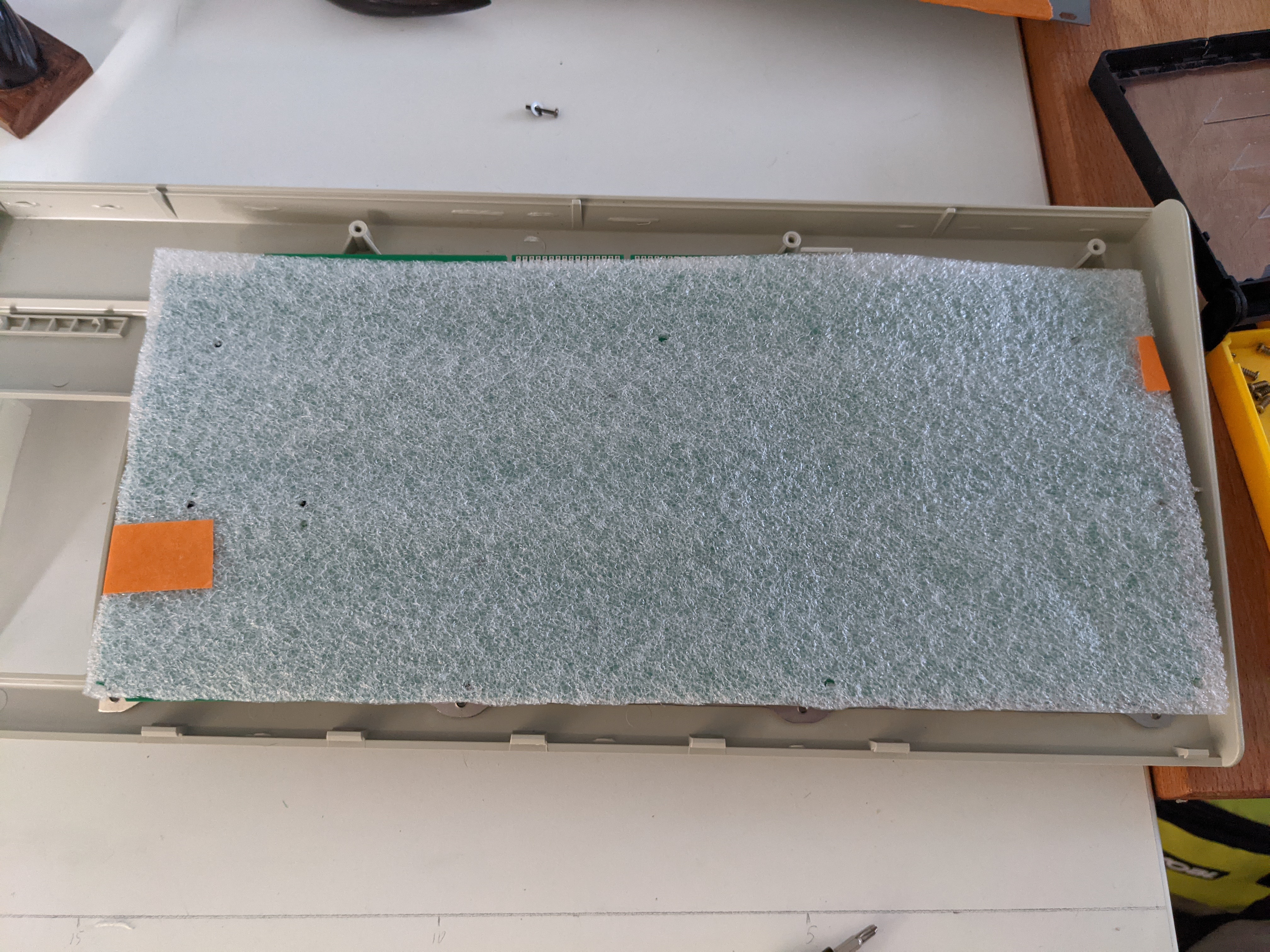
- PXL_20230524_000333345.jpg (3.72 MiB) Viewed 61689 times
didn't seem to affect things much - although it does _somewhat_:
https://youtu.be/w1DxK8ovW9U
That video is unnecessary long, but if it's less than 1 minute, youtube makes a "short" out of it

Try to guess which keys have a blob of silicone on the underside of the barrel. There are 4, and they are pretty easy to spot. Strange thing, however, is that sound level meter app doesn't seem to be able to take those apart AT ALL (shows around 66dB press, around 70dB release). I'll try to find a better microphone, record sounds and do FFT on them to see if it's something to do with sound spectrum emitted.
NOTE: the F122 has no foam - this might affect sound a bit, especially the rebound (keypress - no so much, because the flipper strikes the PCB which is rigidly mounted to the bottom plate, so the energy is freely transmitted, no dampening at all)
You may notice that some of the modded keys are quieter on the keypress than others. That's because some of the blobs are large enough to press the flipper partway down from it's resting position, so it has less space to accelerate in. So the flippers can be molded to be a bit (actually, A LOT) lower in the resting state (in the picture below just the upwards bend of the flipper body is removed, to illustrate the concept. The flipper body will also need to be modified to allow it to rest flat against the PCB.)

- the silence of the Fs.png (31.98 KiB) Viewed 61689 times
The "rebound buffer" will be a small silicone bead with a stem that will go into the barrel body. As you can see from the video, that will virtually eliminate the "key up" sound.
Re: Modeling an F key mechanism
Posted: 26 May 2023, 16:54
by thefarside
Very cool and thanks for the reply. I agree I’m probably in the minority of folks who want a quiet model F. I use a model M for work around others and leave the F to fortress of solitude

Regarding the “dampening ramps”, I’m referring to the extra area the model M has to stop the key stem from going all the way down. The model F doesn’t have anything there and I think pandrew showed if this is shaved off it makes an M louder and has full travel like an F.
I don’t think this would be possible and when I have some free time I’ll try to experiment with it, but I wonder if an insert like a piece of thick paper inside the barrel, or a dab of silicone in there would also dampen the spring click sound.
I’m also curious if the flippers could be made out of something slightly softer that would dampen the smack against the PCB but still be conductive.
Regardless this is very cool and makes me wonder what else is possible in the buckling spring universe. I won’t divert anymore

Re: Modeling an F key mechanism
Posted: 26 May 2023, 18:34
by Muirium
thefarside wrote: ↑26 May 2023, 16:54
makes me wonder what else is possible in the buckling spring universe.
The extended buckling springiverse, I like it.

Re: Modeling an F key mechanism
Posted: 26 May 2023, 19:26
by DMA
thefarside wrote: ↑26 May 2023, 16:54
I’m also curious if the flippers could be made out of something slightly softer that would dampen the smack against the PCB but still be conductive.
Nope, bending stress will kill them.
Re: Modeling an F key mechanism
Posted: 26 May 2023, 22:04
by Muirium
How about steel? #solenoidclub
Re: Modeling an F key mechanism
Posted: 26 May 2023, 22:36
by DMA
Muirium wrote: ↑26 May 2023, 22:04
How about steel? #solenoidclub
Yeah, for the silent version steel is just the ticket.
Re: Modeling an F key mechanism
Posted: 26 May 2023, 23:03
by Muirium

Honestly, though, I think silencing F is a quixotic endeavour. You can take the edge off it, but it’s still a riot of a mechanism. Others, fortunately, are available.
Re: Modeling an F key mechanism
Posted: 28 May 2023, 00:21
by DMA
Muirium wrote: ↑26 May 2023, 23:03

Honestly, though, I think silencing F is a quixotic endeavour. You can take the edge off it, but it’s still a riot of a mechanism. Others, fortunately, are available.
What's so "unrealistic and impractical" about it? Buckling spring mechanism was created for the feel, not sound.
Anyhow, a neighbor got me an
UMIK-1, so I'm gonna do some actual noise level measurements and record waveforms to compare. Good thing I didn't throw away all that fat polyurethane foam I used as packing material for that truckload of oscilloscopes I brought from Alabama two years ago - those will be used for a clowny anechoic chamber.
Re: Modeling an F key mechanism
Posted: 28 May 2023, 15:04
by Muirium
Model F is one of the loudest switch mechanisms ever made. Silencing that is quite a windmill to tilt, Don Quixote.

IBM was explicitly targeting the Selectric feel
and sound with their computer keyboards. The Beamsprings, from which these were derived, had a solenoid for a reason: to be as responsive and LOUD as an electric typewriter. Typists were used to the vibration and the racket on every keystroke. Model F dialled it down a bit, but not much. And actually, F is much more resonant.
The upside I suppose is that with all that noise, there’s a lot of scope for quiet improvement!
