Anyone familiar with how manufacturers implemented special features on the PS/2 protocol?
Posted: 19 Dec 2023, 18:58
If you don't care about the long-winded backstory of my project, scroll down to the section labeled "Skip here for the actual question".
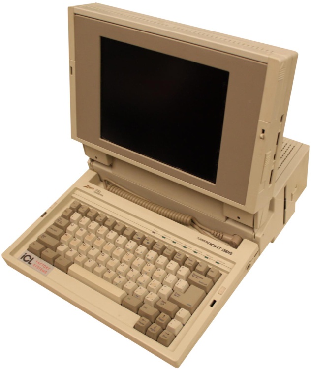
I'm working on a retrofit project involving a Zenith Turbosport 386. I set myself a limitation that I couldn't do anything to it that couldn't be undone in the future. Part of that has been adapting it's XT 5 pin DIN keyboard to USB. But I also wanted to be able to remap keys because some of the keys I use a lot are not easily accessible. For instance, F12 is accessed via Fn+F2. I also wanted to be able to add macros and map a windows key. I stumble across this forum and the excellent Soarer's firmware. Since there were turnkey versions of this on eBay, I decided to go that route and bought a 5 pin DIN to USB cable that had the microcontroller integrated and the firmware already flashed.
Unfortunately, that proved to be unreliable. It seemed that most times that I plugged it in, it would detect my keyboard incorrectly and many of the keys would be mapped to weird keys. I'd have to unplug and replug in the keyboard many times to get all the keys to finally work. Not ideal.
Long story slightly less long, I decided to roll my own. With a Seeed Studio Xiao and copious amounts of googling and trial and error, I have a functional keyboard that works correctly every time it's plugged in. I still have some small things to overcome, but I'm typing this on it now. It works well. That brings us to my actual question:
--Skip here for the actual question --
The keyboard has extra LED indicators for Power, Hard Drive, and Floppy Drive. There are no extra wires in the original cabling, so I have to assume that the computer sends regular PS/2 commands to the keyboard just like the other LEDs. I had hoped that they just used the next value up from where the standard LED indexes stop, but unfortunately, that didn't work. Does anyone know what they might have used? I have 2-way communication with the keyboard working. I can control the LEDs for Num Lock, Caps Lock, and Scroll Lock with no issue. I've also found that if I send 255 as the LED index value, all of the lights is flash on, then off. I think that's the keyboard resetting. So I may be causing the keyboard controller to get confused or to overflow or something. Also, some values in the 200's will lock the keyboard up until it's power cycled.
If nobody here knows, I may see if I can hook something up to the original hardware and see what it sends for the power on LED. That's all I'll be able to check though. I'm retrofitting this computer because I was unable to get the original hardware to boot. Even after purchasing 3 different units to try to troubleshoot. But it will, at least, turn on the power LED on the keyboard.