Page 1 of 1
Help with designing a PCB?
Posted: 11 May 2014, 14:28
by sipth
Hi guys! I want to make a small keyboard to bring about just for my game controls but i know nothing about PCBs so I was wondering if it's possible if you guys can help me. I want to keyboard to be 5x5(
)
I dont think I'll be getting it plate mounted as that would just add up to the cost and something this small shouldnt flex too much. As for ordering it, I'm not sure where I should get it from, most probably PCB, not sure if there is a cheaper option.
thanks!
Posted: 11 May 2014, 15:09
by ne0phyte
Do you have any specific questions?
If you want to learn how to and create the PCB on your own you should
download KiCad.
I don't know if there are better tutorials, but here are the resources I used to get into KiCad:
-
https://github.com/BathroomEpiphanies/K ... -Tutorial/
(footprints.mod & components.lib = switches, teensy2, diode)
-
https://raw.githubusercontent.com/regac ... Basics.pdf
(A bit annoying to follow, but explains how to make a basic matrix of switches with diodes)
I didn't follow that PDF exactly but used it more as a guide for the general workflow (schematic -> netlist -> pcb design).
There is also a wiki article on this:
http://deskthority.net/wiki/KiCAD_keybo ... sign_guide
And here you can see one way to mount a Teensy2.0 controller:
http://deskthority.net/wiki/Phantom_ins ... nstruction:
This should be enough information to get started making a basic matrix PCB.
Posted: 11 May 2014, 15:11
by sipth
Wow, thanks alot! I'll try it out! What I'm afraid is that the one I ordered wouldn't work the there goes my $45. I'll try it out and ask questions as i go!

Posted: 11 May 2014, 15:15
by ne0phyte
There is a "Design Rules Check" in KiCad that finds possible problems and you can post your PCB here and let someone have a look before ordering one. I only finished my first PCB a week ago for my
40% keyboard so I have very little experience with this as well but there are other people on Deskthority who designed PCBs before

EDIT: Oh and it seems that the wiki is being updated right now so the two wiki links aren't available at the moment.
Posted: 11 May 2014, 15:19
by Muirium
Well, you might just want to grab this:
http://www.ebay.co.uk/itm/130541363513? ... 1436.l2649
The switches are not Cherry MX, but the caps are quite nice and you've basically got everything you're looking for, apart from the double-sized corner key. That would solder up with a Teensy quite the trick.
Someone posted about those 5x5 switch sets on the forum recently. Can't remember if the caps are MX compatible. But even if they're not, it's a cheap way to skip straight to a prototype!
Posted: 11 May 2014, 15:23
by sipth
ne0phyte wrote:There is a "Design Rules Check" in KiCad that finds possible problems and you can post your PCB here and let someone have a look before ordering one. I only finished my first PCB a week ago for my
40% keyboard so I have very little experience with this as well but there are other people on Deskthority who designed PCBs before
EDIT: Oh and it seems that the wiki is being updated right now so the two wiki links aren't available at the moment.
Ohh no wonder I couldn't go to the website. May I know where you got your PCB from? and how much did it cost you?
Muirium wrote:Well, you might just want to grab this:
http://www.ebay.co.uk/itm/130541363513? ... 1436.l2649
The switches are not Cherry MX, but the caps are quite nice and you've basically got everything you're looking for, apart from the double-sized corner key. That would solder up with a Teensy quite the trick.
Someone posted about those 5x5 switch sets on the forum recently. Can't remember if the caps are MX compatible. But even if they're not, it's a cheap way to skip straight to a prototype!
So that is basically a non cherry mx 5x5 keyboard?
Posted: 11 May 2014, 15:27
by Muirium
Yes. Without PCB, so it's just switches and a plate. Ready for you to wire up any way you like.
I don't know why they exist, but they do!
Posted: 11 May 2014, 15:30
by sipth
Haha yea, it's kinda random that they exist. I know for sure that I'll be able to build the case myself using my school's workshop, I dont know if they have a machine to cut metal tho. I guess now the hardest part for me is to design a PCB for it.
Posted: 11 May 2014, 15:30
by ne0phyte
sipth wrote:Ohh no wonder I couldn't go to the website. May I know where you got your PCB from? and how much did it cost you?
I ordered mine on
http://www.jackaltac.com and paid 78€ for 2 PCBS of 227x76mm with shipping. There is a calculator online and one 100x100mm (roughly the minimum a 5x5 matrix could be) is 35€ for one and 50€ for two without shipping. For me the shipping was like 8€ so you could probably get one for 44€ / two for 58€.
Posted: 11 May 2014, 15:49
by Muirium
There is the no-PCB option too:
 http://deskthority.net/workshop-f7/the- ... t1067.html
Just add diodes and wires. I've done this a few times now, and it is as fiddly as it looks, but for a little 5x5 matrix it'd be quite easy.
Anyway, if learning PCB design is what you're really up to, carry on!
Posted: 11 May 2014, 15:52
by sipth
Ohh sweet, price seems similar to PCBwing, I think PCBwing might just be cheaper.
Ohh man... the program looks really complicated and I'm alr getting a headache from learning autocad in school haha.
What do you call wiring the switches like that? Do you have a link or a tutorial for it? Seems like it requires a plate to mount it on which I dont think I'll be able to get haha.
Posted: 27 Jun 2014, 13:04
by solkoseryl
Hello guys,
I've got a schematic question, if you don't mind.
I'm trying to create my first keyboard, and following the ne0phyte's link list (thank you so much for collecting everything useful in one place!).
So far I've finished the switch/diode matrix in the eeschema — I've got 6 rows and 22 columns = 28 lines. But the Teensy2 controller has only 25 legs to connect the rows/columns, if I get it right (PB0..7, PC6..7, PD0..7, PE6, PF0..7 = 25 legs plus RST, AREF, 2*VCC, 2*GND). Happily, I don't need in LEDs at all.
Should I choose another controller, or is there some trick to solve this problem?
(I have empty cells in the matrix, so I could make things more tight and squeeze the matrix to 6 rows, 21 columns = 27 lines, but it would lead to further circuitry tangling, I'm afraid, and won't be the answer to this question anyway)
Thanks in advance for the answers!
Posted: 27 Jun 2014, 14:00
by Game Theory
Posted: 27 Jun 2014, 14:14
by Muirium
Teensy ++ is the one I'd go for, because I could run Soarer's controller on it. Maybe Hasu's TMK compiles for Teensy 3? I don't know. Haven't tried it myself. Teensy 3 is ARM while Teensy 2 and ++ are ATMEGA, so very different in fact.
Also: remember to skip the Teensy's built in LED pin. It's no good as an input, without hacking the hardware.
Oh, and put your numpad on the left. It'll be so much better!
Posted: 27 Jun 2014, 15:35
by Findecanor
You have 105 switches. As a general rule, the matrix with the least number of (rows+columns) would be as square as possible. The smallest square that would fit 105 switches is 10×11 (110 positions, 21 lines).
You could stretch that matrix out vertically and merge adjacent columns. You would have to move some switches between columns because there are only 5 empty positions compared to 27 in your original matrix.
Posted: 27 Jun 2014, 16:07
by Muirium
When hand wiring my
63 key custom keyboard, I lazily made a 15x5 matrix, which is only 84% utilised. Of course, 20 pins was within the Teensy 2's reach anyway, so I had no reason to complicate matters. When designing your own PCB, though, you can be the judge. Teensy++ isn't cheap!
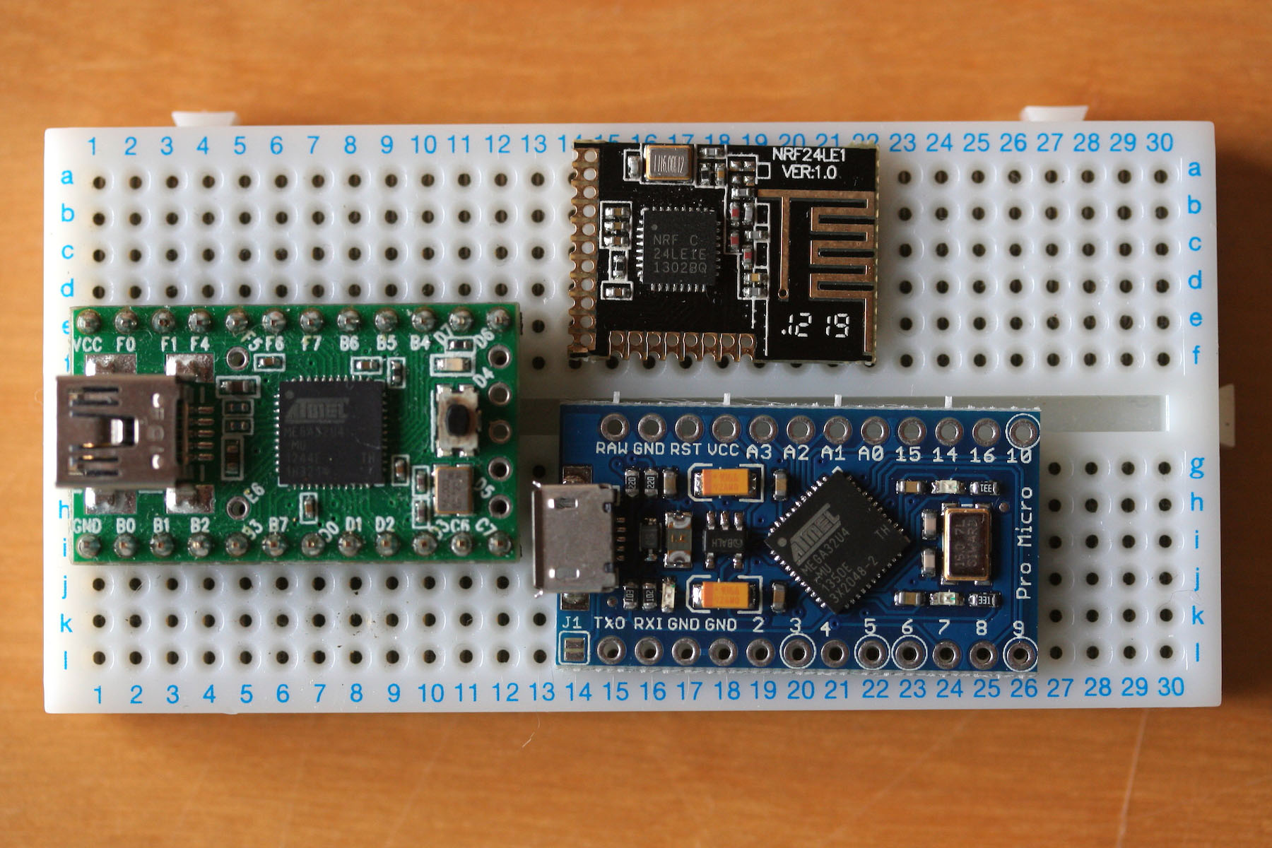
My current project is using a PCB and a highly optimised matrix, because I have even fewer pins to play with on this little wireless controller…
Posted: 27 Jun 2014, 21:34
by solkoseryl
Game Theory wrote: teensy 2++ or teensy 3.x ?
Muirium wrote: Also: remember to skip the Teensy's built in LED pin. It's no good as an input, without hacking the hardware.
Findecanor wrote: As a general rule, the matrix with the least number of (rows+columns) would be as square as possible. The smallest square that would fit 105 switches is 10×11 (110 positions, 21 lines).
Thank you for the tips, guys!
First, I'll try to connect the Teensy 2.0++ and continue with the KiCad modelling. After finishing that, I'll try to rework the matrix as Findcanor suggested and manage with Teensy2.0. So I could understand which way is the best.
And now a couple of questions again, sorry

Is there any chance to get the single-sided PCB? Or should it be at least double-sided or even the multilayer one?
And Teensy's LED, will it work permanently? Is there any way to turn it off?
Muirium wrote: Oh, and put your numpad on the left. It'll be so much better!
I'm limited with the shape of the case — and I like the LK201-like layout!

Posted: 27 Jun 2014, 21:41
by Muirium
I bet you mouse with your left hand then! I can't handle those big layouts unless I swap mouse hands.
Almost every keyboard PCB I have seen is double sided. One layer for the columns, and the other for the rows. Matteo hand made a nice single sided one using diodes to bridge the two. It's harder, no doubt, but if you want to win a challenge…
The Teensy's LED can be disabled by attacking it with a soldering iron! It's just surface mount on solder, like the USB header, and can be hacked if you prefer to see it gone. Once out the way, that pin is all yours. Its only function really is as a programmable status light.
Posted: 27 Jun 2014, 23:00
by Findecanor
AFAIK, all of
Cherry's own keyboards with PCB-mounted MX-switches are single-sided but most of them are actually manufactured double-sided with the top-facing side as a single ESD/ground plane connected to the wire's shield. If there was a plate, the plate would be connected to shield instead.
You could route lines in-between the legs of the switch or in-between the legs of a diode or in-switch jumper. Cherry's keyboards do that a lot, but they also often have many additional jumper wires to cross lanes.
Will one-sided be significantly less expensive than double-sided? I see no reason to go more than two layers.
Posted: 28 Jun 2014, 02:22
by solkoseryl
Murium, Findecanor, thank you for the useful info about sides!
Findecanor wrote: AFAIK, all of
Cherry's own keyboards with PCB-mounted MX-switches are single-sided but most of them are actually manufactured double-sided with the top-facing side as a single ESD/ground plane connected to the wire's shield. If there was a plate, the plate would be connected to shield instead.
I'm trying to create the new PCB for the old WYSE terminal keyboard, it's switches are plate mounted and the plate is connected with the PCB ground; I want to do exactly the same.
So far - so good. Please, help me to clear one more thing I'm stuck with. Teensy 2++ has 2 VCC legs and 3 GND legs. I connected each VCC leg with VCC component from library and each GND leg with power port. I've called them: "Component Ground - #PWR01", "Component Ground - #PWR02", "Component Ground - #PWR05", "Component VCC - #PWR03", "Component VCC - #PWR04".
But Electric Rules Check said:
Code: Select all
ErrType(3): Pin connected to some others pins but no pin to drive it
    @ (97,79 mm,69,85 mm): Pin 1 (power_in) of component #PWR04 is not driven (Net 42).
and highlighted one of GNDs (pin1) and one of VCCs (pin52) with the green arrows.
What am I doing wrong?
Thank you in advance for the tips!
Posted: 28 Jun 2014, 20:52
by chzel
Muirium wrote: Well, you might just want to grab this:
http://www.ebay.co.uk/itm/130541363513? ... 1436.l2649
The switches are not Cherry MX, but the caps are quite nice and you've basically got everything you're looking for, apart from the double-sized corner key. That would solder up with a Teensy quite the trick.
Someone posted about those 5x5 switch sets on the forum recently. Can't remember if the caps are MX compatible. But even if they're not, it's a cheap way to skip straight to a prototype!
Thank you for that find Muirium!!
Even if the switches are crap, or the cap incompatible, the plate is compatible!
14x14mm with 19mm CtC!!


Posted: 19 Jul 2014, 00:01
by cilek
@sipth: Hi , if you are new in the PCB design then I think you should go with the proteus because you have to draw the circuit diagram of the project and then it will convert the design into the PCB layout otherwise you can use the other free software like Eagle, KiCAD etc.
circuit card assembly