Page 4 of 24
Posted: 26 May 2015, 19:07
by Muirium
Or full, then taken one by one to the recycler. Nightmares are dreams too.
Posted: 26 May 2015, 19:12
by Khers
At least, bankers don't run Unicomp afaik...
Posted: 26 May 2015, 20:16
by Redmaus
seebart wrote: Yes, you are allowed to dream Redmaus.
My dream will be arriving soon actually

Posted: 26 May 2015, 20:22
by bhtooefr
You know, one concern I've got with using the stock Model M plastic barrel plate is that... doesn't the stock metal top plate with separate barrels on an F act as an RF shield?
I could see nasty problems with sensing and with RFI without that in place.
Posted: 26 May 2015, 20:43
by idollar
bhtooefr wrote: You know, one concern I've got with using the stock Model M plastic barrel plate is that... doesn't the stock metal top plate with separate barrels on an F act as an RF shield?
I could see nasty problems with sensing and with RFI without that in place.
I cannnot see how RF shall affect such a big capacitor ... but I may be wrong here.
Posted: 26 May 2015, 20:47
by idollar
Alright ... lets come back to the PCB creation and its layout.
Here is the research that I have done so far.
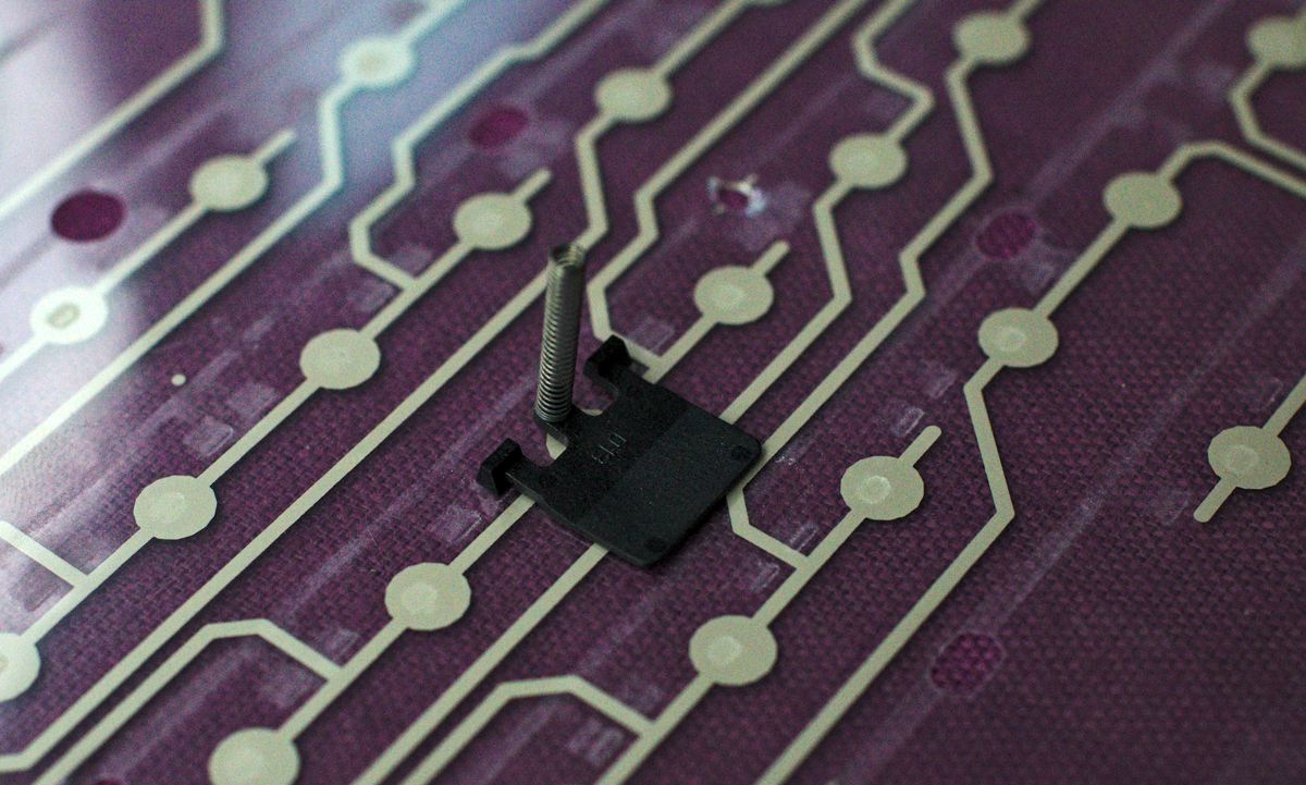
The pivoting points of the flippers in the barrels are not exactly in the centre. They are just above it.
If I paint this in the bifoot PCB, before the flipper is tested, I get the following:
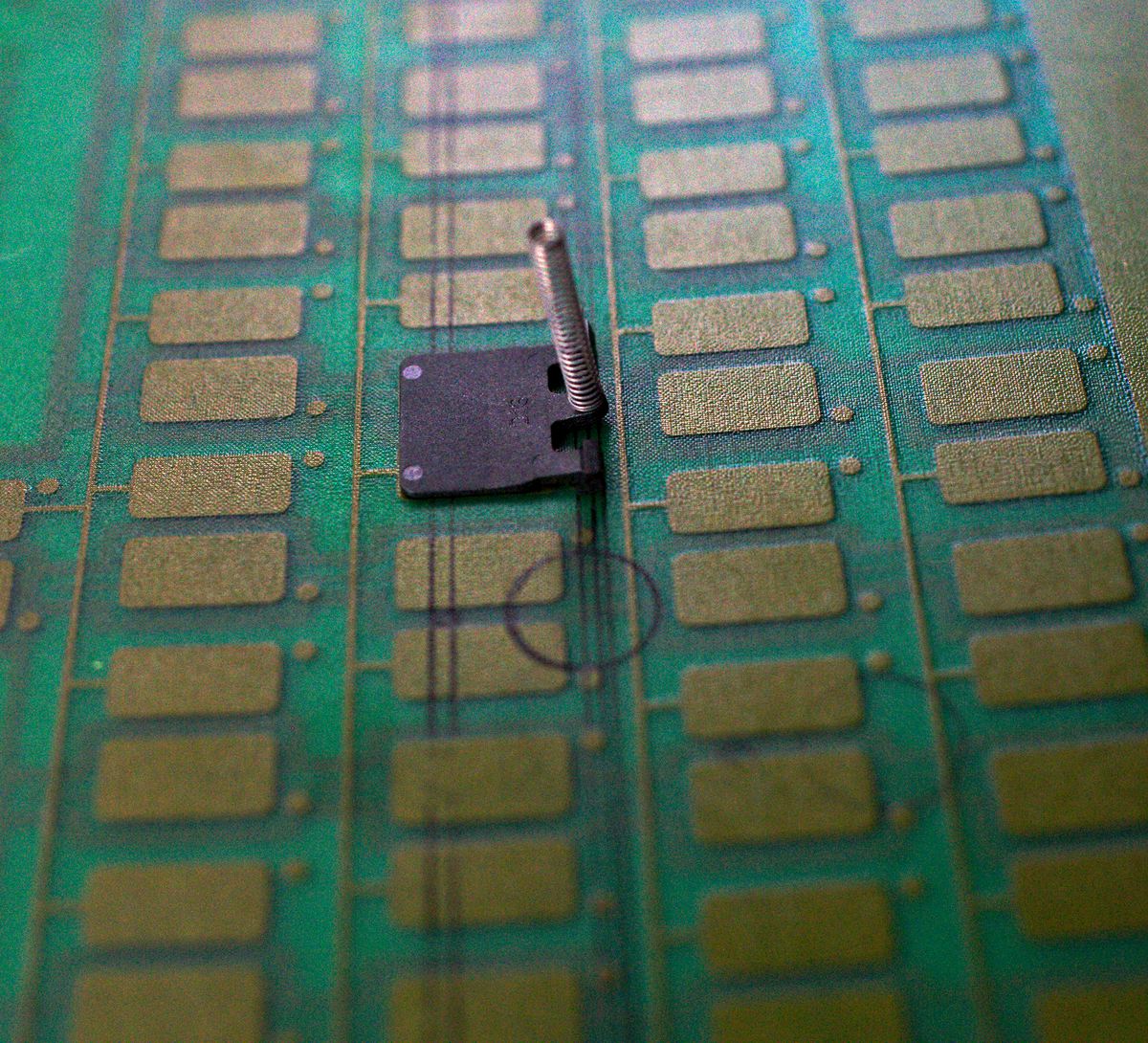
- DSC_2869.jpg (321.06 KiB) Viewed 9475 times
- DSC_2871.jpg (157.66 KiB) Viewed 9475 times
You can see that my observation was correct. The foot of the flipper exactly covers the capacitor:
- DSC_2872.jpg (139.07 KiB) Viewed 9475 times
Posted: 26 May 2015, 20:50
by idollar
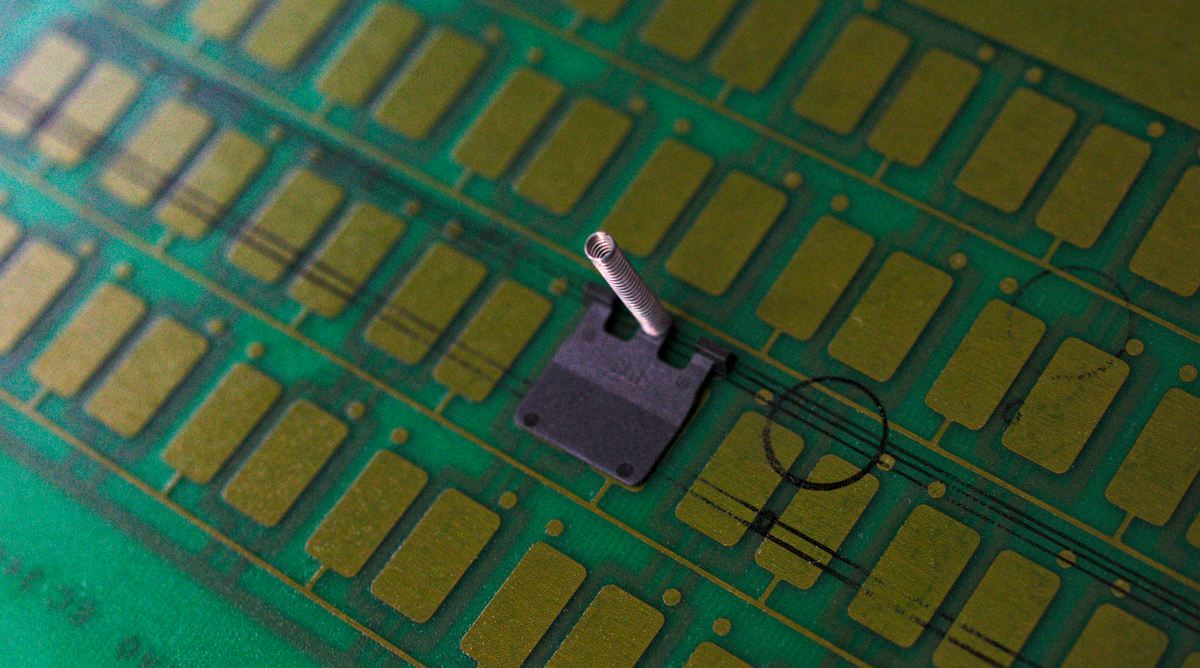
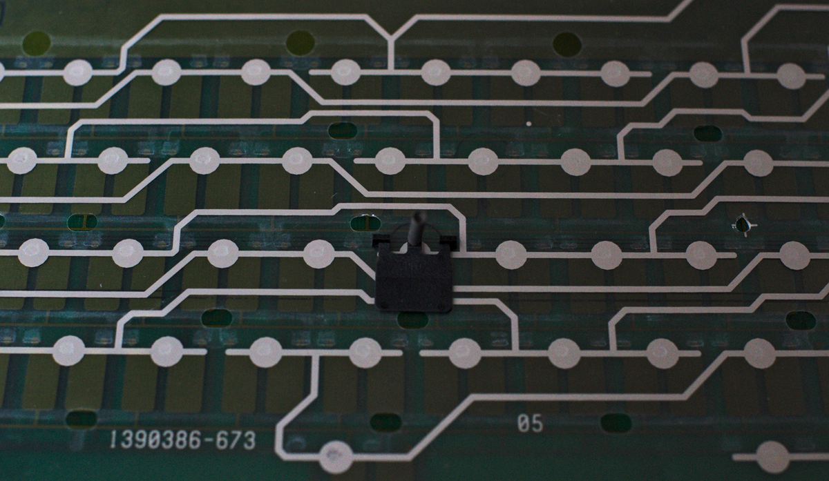
Now we can move to the SSK: the membrane has clear marks of the flipping points of the flippers that can be used to position the F flippers and check how would they sit on top of it:
- DSC_2873.jpg (164.23 KiB) Viewed 9471 times
I send you a second picture without the nasty reflection. You may see better what I mean:
- DSC_2874.jpg (170.66 KiB) Viewed 9471 times
You can see the the top part of the flipper foot is aligned with the conductive line and therefore with the centre of the contact point in the SSK membrane. This is very good news. We have a simple reference on the membrane,
Posted: 26 May 2015, 20:53
by idollar
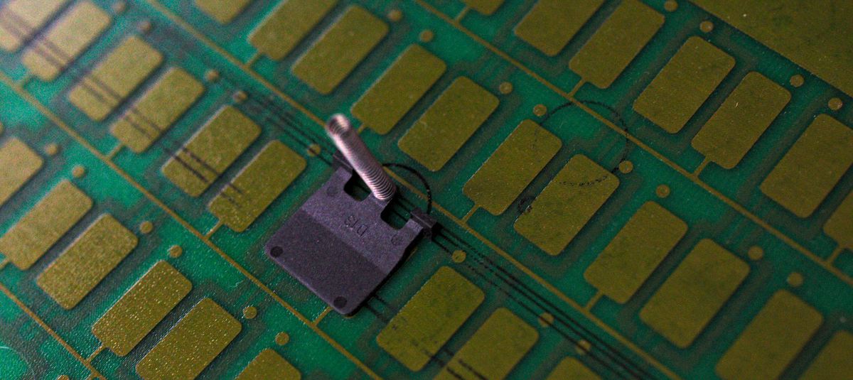
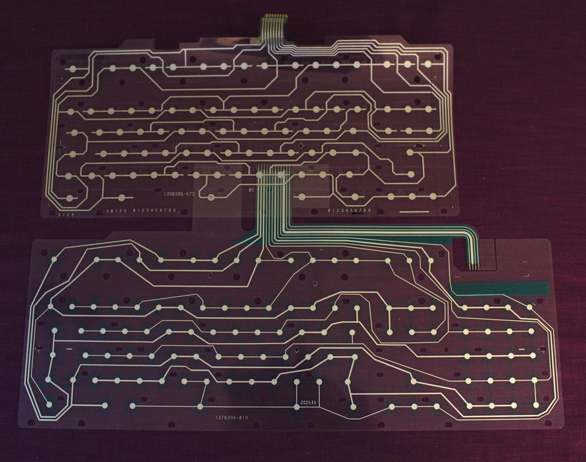
If we put all together (the membrane is transparent) we can see how the PCB should look like with respect to the distribution of the keys in the SSK.
- DSC_2875.jpg (131.81 KiB) Viewed 9468 times
The next step is therefore to model the SSK membrane first using the right software that produces the required file format for the company doing the prototype PCB. We could create this as a "virtual" layer that will latter be deleted. We add the two capacitor layers on top, using the references that we have found, link them ensuring that the holes for the screws are not in the middle, create the connector and we will be done.
Comments ?
Posted: 26 May 2015, 20:58
by XMIT
I think adding the membrane is an unnecessary intermediate step that could lead to dimensional errors.
Since both the Model M and Model F barrels are basically identical this should be enough information:
- relationship of positions of capacitive pads to center line of Model F barrel
- locations of centerlines of Model M SSK barrels.
Posted: 26 May 2015, 21:02
by idollar
XMIT wrote: I think adding the membrane is an unnecessary intermediate step that could lead to dimensional errors.
Since both the Model M and Model F barrels are basically identical this should be enough information:
- relationship of positions of capacitive pads to center line of Model F barrel
- locations of centerlines of Model M SSK barrels.
XMIT, That's exactly what I have done/suggested.
- the location of centerlines of model M SSK barrels is given by the centre of the contact point in the membrane (with a vertical displacement). We could simply use the membrane as our template for the barrels positions. The fact that is flat and transparent will help a lot. Measuring the barrel plate may lead to mistakes.
- the relationship of the positions of the capacitive pads to the centre line of the Model F barrel is show in the last picture.
Feel free to criticize this approach ... we might find a better way
Posted: 26 May 2015, 21:06
by XMIT
Yes, I think that makes sense. I think the photo would be clearer with a Model F flipper foot on one contact point and a Model M flipper foot on the adjacent contact point. I had to think about what a Model M flipper foot looks like, where it pivots, and where the strike point is on the underside.
But, if you can use the membrane as a guide, that would be best. You know it is correct, it is transparent, etc. I may suggest scanning it on a flatbed scanner and then using it as a template in whatever CAD program you use as you proposed earlier.
Sounds great!
Posted: 26 May 2015, 21:09
by idollar
XMIT wrote: I may suggest scanning it on a flatbed scanner and then using it as a template in whatever CAD program you use as you proposed earlier.
Good idea !!! I may use an spare Unicop membrane that I have somewhere. It is flat.
I just have to make sure that it exactly matches the SSK (it should). I will have to remove the number pad.
Posted: 26 May 2015, 21:21
by idollar
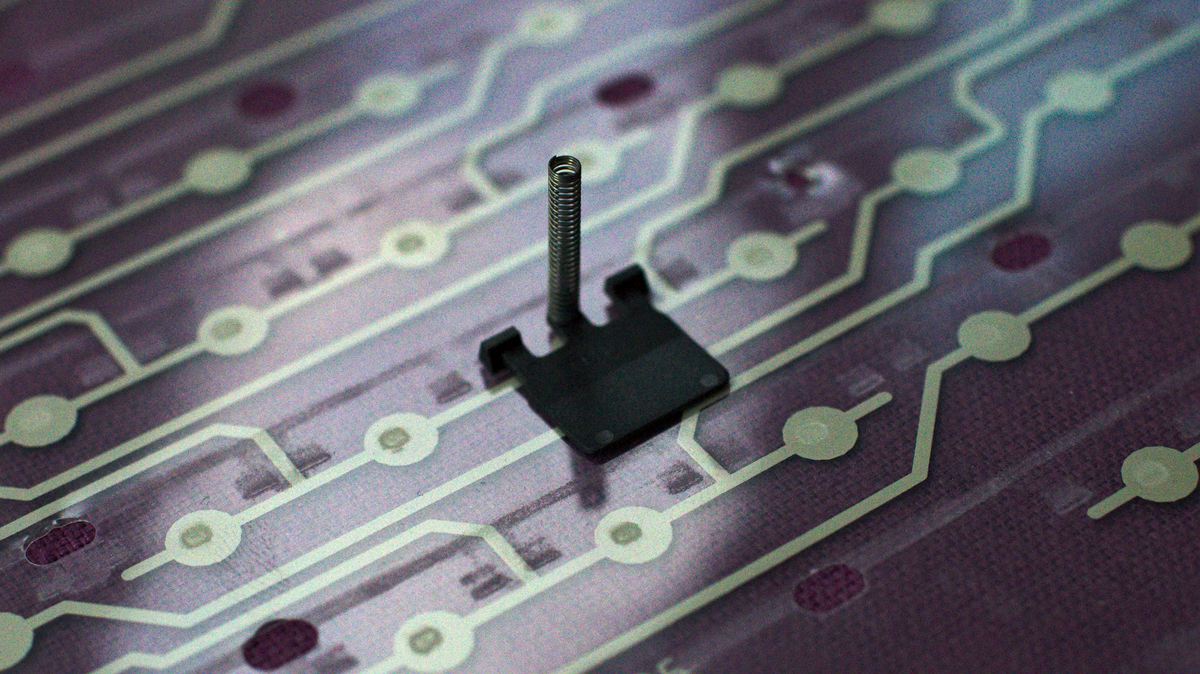
As expected the unicomp membrane and the ssk have the same distribution
- DSC_2876.jpg (187.26 KiB) Viewed 9442 times
The unicomp one has lines marked which ease even more finding the centre of the contact point !
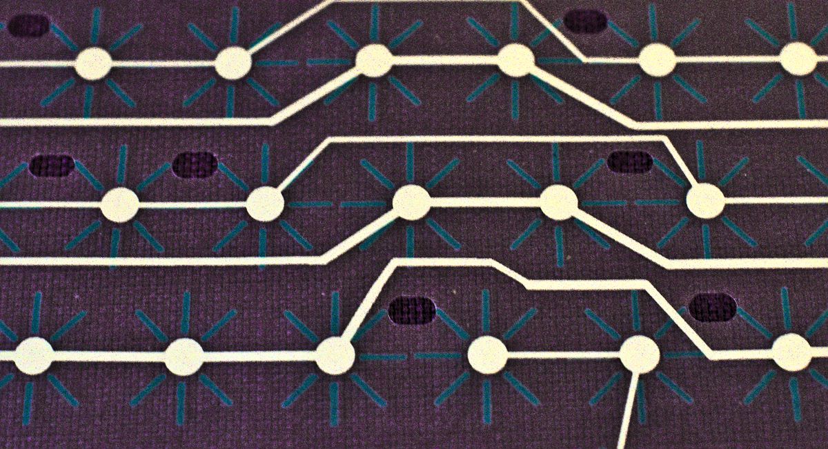
- DSC_2877_01.jpg (220.33 KiB) Viewed 9442 times
(apologies for the quality of the pictures, I am working without light and in real time.)
Posted: 26 May 2015, 21:52
by Muirium
Are you working under the assumption that Model F cap sense pads should be centred on the same alignment as Model M membranes? The flippers are different sizes, I expect the Model F pads are a bit lower down the board so they lie dead centre under each lare flipper. Just a guess though.
Did Wcass share his XTant PCB design file with you? Can't remember if it's open source.
Posted: 26 May 2015, 22:01
by idollar
Muirium wrote: Are you working under the assumption that Model F cap sense pads should be centred on the same alignment as Model M membranes?
No I am not. Read above again. I guess that this was already answered.
The common reference point is in the center of the barrel or the spring.
Posted: 26 May 2015, 22:05
by Muirium
Ah right, I was reading on the phone and never saw your other posts. Just the last one alone.
Posted: 26 May 2015, 22:11
by idollar
Muirium wrote:
Did Wcass share his XTant PCB design file with you? Can't remember if it's open source.
We already had some PMs exchange. I have a PDF with his PCB layout. Unfortunately both layers are together making the analysis complicated. I also miss the references in the barrel plate.
Posted: 26 May 2015, 22:57
by bhtooefr
idollar wrote: I cannnot see how RF shall affect such a big capacitor ... but I may be wrong here.
It's both RF getting into the capacitors (because the sensing works using a decently high frequency scanning frequency, and measuring how much charge the capacitors are storing, IIRC - stray RF can affect that), as well as RF coming from the keyboard and affecting other things (said decently high scanning frequency) that is a concern.
Posted: 27 May 2015, 09:46
by idollar
bhtooefr wrote: idollar wrote: I cannnot see how RF shall affect such a big capacitor ... but I may be wrong here.
It's both RF getting into the capacitors (because the sensing works using a decently high frequency scanning frequency, and measuring how much charge the capacitors are storing, IIRC - stray RF can affect that), as well as RF coming from the keyboard and affecting other things (said decently high scanning frequency) that is a concern.
If I am not mistaking, the Xtant used a non-metallic board to hold the barrels. And it worked.
I am not very worry about this, but it may be worth looking again at the Xtant thread to see how it was done.
Posted: 27 May 2015, 10:06
by idollar
http://deskthority.net/post71229.html#p71229
the test acrylic barrel plate is in. it is still flat and covered with protective paper, but i could not resist checking it out with barrels and keys. i think it looks pretty good.
Re: Let's create the FSSK !
Posted: 27 May 2015, 10:08
by Nuum
That concerns the "Model W", not the Xtant, the Xtant used a curved metal barrel plate as well as the original XT back plate AFAIK.
Posted: 27 May 2015, 10:13
by idollar
http://deskthority.net/post208600.html#p208600
I was wrong. The Xtant has a metal barrel plate:
The top plate = the barrel plate.
I did mine with 18 gauge CRS, but stainless would work too. You want something close to .05" (1.25mm) thickness. The link below has a DXF flile for making that.
https://github.com/wcass-/XTant/tree/master/XTant
XT/Bigfoot use a pin/hole to lock the barrel against rotation; AT/122/Kishsaver use a bulge/notch to lock the barrel from spinning. In a pinch, you can use an XT barrel in an AT/122/Kishsaver by cutting off the pin at the base. The only thing preventing it from spinning would be other barrels so best to put it as a middle column and middle row.
Thought I would throw out that 3178's use a pin. Also until a couple days ago I had no idea there were different barrels. The more you know.gif
Posted: 27 May 2015, 16:28
by Muirium
Yup. That plate is the one missing component in my own XTant project. Dorkvader got held up when ordering some for the rest of us with Wcass's kit.
I've successfully typed on a capsense NovaTouch (Topre inside) just by touching my fingers against the pads on the bare PCB, not even installed in a case! Capsense isn't too bothered about stray signals, at least in that experience. I know it can be very picky about dirt inside a keyboard, though. Analog is complex!
While I had that NovaTouch open (I was installing a Caps Lock LED) and powered up for testing, I didn't notice any interference in my other hardware. My Bluetooth Magic Mouse still worked fine. I don't think leakage out from the keyboard poses a problem in reality.
Oh, and about capsense pads: IBM uses 3 or 4 of them. They are on both sides of the PCB. At least one of the pads you can see is passive, and doesn't connect to the controller or anything else. Xwhatsit explained their system to me at one point, I can dig out his description.
Posted: 27 May 2015, 19:21
by idollar
Muirium wrote:
Oh, and about capsense pads: IBM uses 3 or 4 of them. They are on both sides of the PCB. At least one of the pads you can see is passive, and doesn't connect to the controller or anything else. Xwhatsit explained their system to me at one point, I can dig out his description.
Please, do it.
Posted: 27 May 2015, 20:54
by Muirium
Finding good links while searching:
http://deskthority.net/post165490.html#p165490
http://deskthority.net/post161394.html#p161394
And check this out: Xwhatsit got his controller working very easily with a
completely different kind of capsense board. Looks like it can handle just about anything!
xwhatsit wrote:
Thanks xavierblak! Never thought to try one of these controllers with a non-Beam/Buckling spring keyboard. I'm surprised how straightforward it has adapted to a very different sensing scenario (linear, no mechanical hysteresis, top-side two-capacitor pad card etc.). What other crusty capacitive boards are out there waiting to be revived?!
The other popular capsense implementation I've seen first hand: Topre, is two pads, single sided as far as I can tell, too. It just uses semicircles instead of rectangles, and they sit on the top side, just under the conical springs they sense.
Posted: 27 May 2015, 20:59
by bhtooefr
I wouldn't expect interference to 2.4 GHz devices, as a Model F doesn't run anywhere near those frequencies (can't quickly find the frequency that IBM used in scanning, but it's probably well under 1 MHz.)
Posted: 31 May 2015, 15:33
by vivalarevolución
Wow, just saw this project. Awesome. I would be interested in a PCB, although I need to come up with some F flippers.
Posted: 31 May 2015, 19:19
by idollar
I am busy at present. It will not progress very fast during the next weeks ...
Those flippers will be the key if it works
Posted: 31 May 2015, 19:53
by vivalarevolución
idollar wrote: I am busy at present. It will not progress very fast during the next weeks ...
Those flippers will be the key if it works
Turns out one or two of my Model Fs has a dead PCB, so that's a donor now. And my SSK has a membrane with creases that causes a couple keys to be defective. So it looks I have another donor there. If you could keep me in mind for when you develop and order the PCB, that would be great. I imagine that could help lower the cost a little, too.

Posted: 31 May 2015, 20:40
by idollar
vivalarevolución wrote: idollar wrote: I am busy at present. It will not progress very fast during the next weeks ...
Those flippers will be the key if it works
Turns out one or two of my Model Fs has a dead PCB, so that's a donor now. And my SSK has a membrane with creases that causes a couple keys to be defective. So it looks I have another donor there. If you could keep me in mind for when you develop and order the PCB, that would be great. I imagine that could help lower the cost a little, too.
Will do. Yes, it will help to lower the cost.
Before ordering the prototype PCBs I will ask in the forum. There are already a couple of interested members.
I guess that the minimum order would be 5. The price to be the first would be to accept the risk of a design mistake or any other problem. I guess that this is understandable.