Typewriter Facit 8121
- Facitman
- Location: Belgium
- Main keyboard: Cherry G80
- Main mouse: Microsoft Intellimouse
- Favorite switch: C.P.Clare SF5101
- DT Pro Member: -
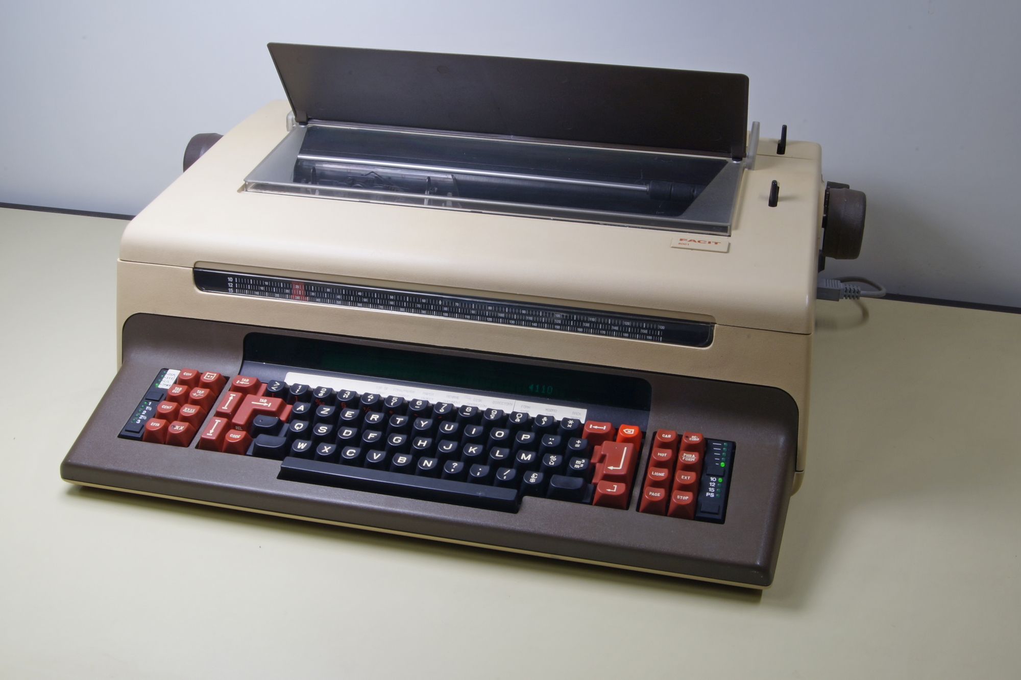
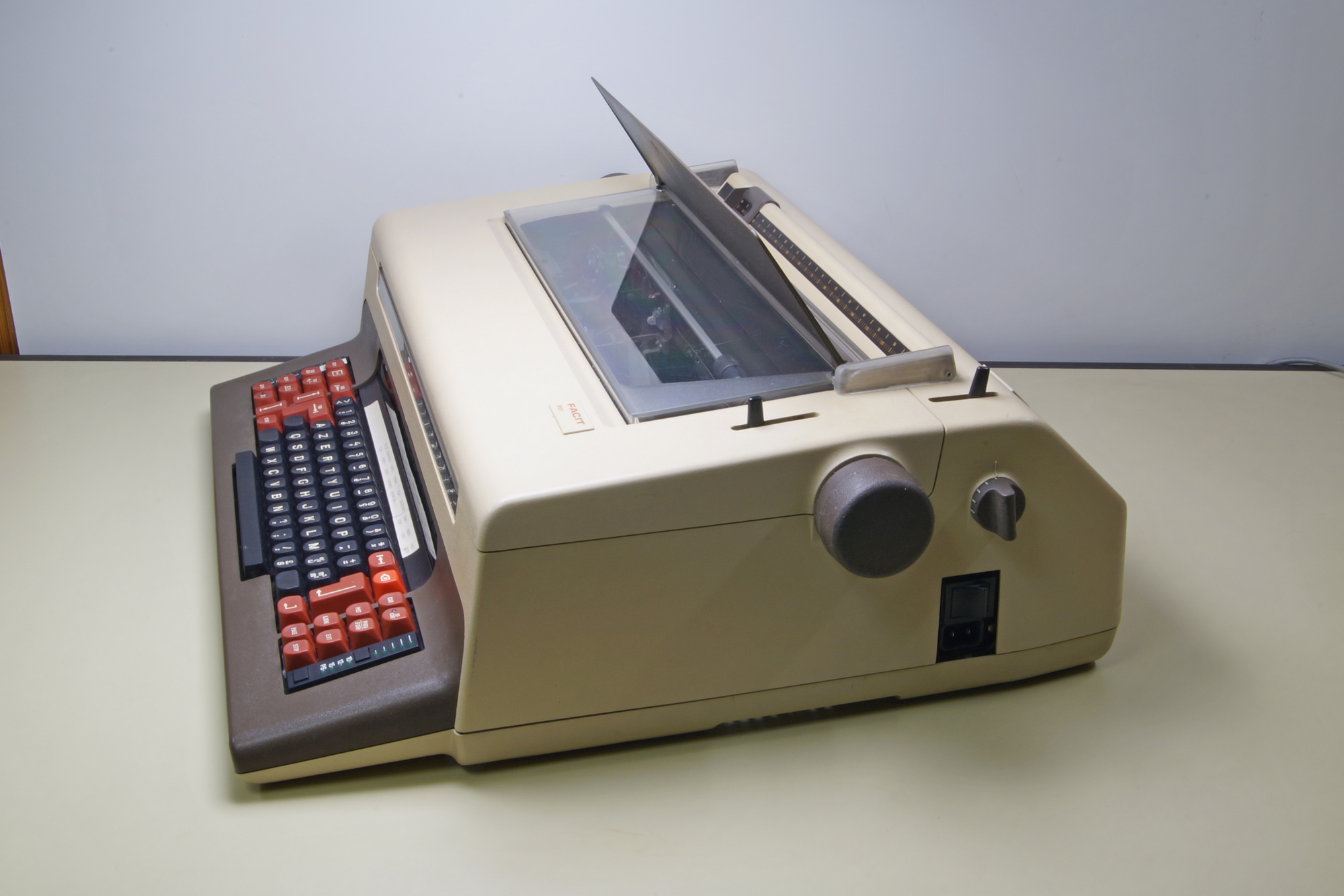
The typewriter Facit 8121.
Another typewriter in the same series as the 8111 presented by Haata photos-videos-f64/facit-8111-2-typewriter-t12424.html and the typewriter/Invoicing machine 6480 presented by purdobol photos-f62/facit-6480-typewriter-calculator-t17719.html
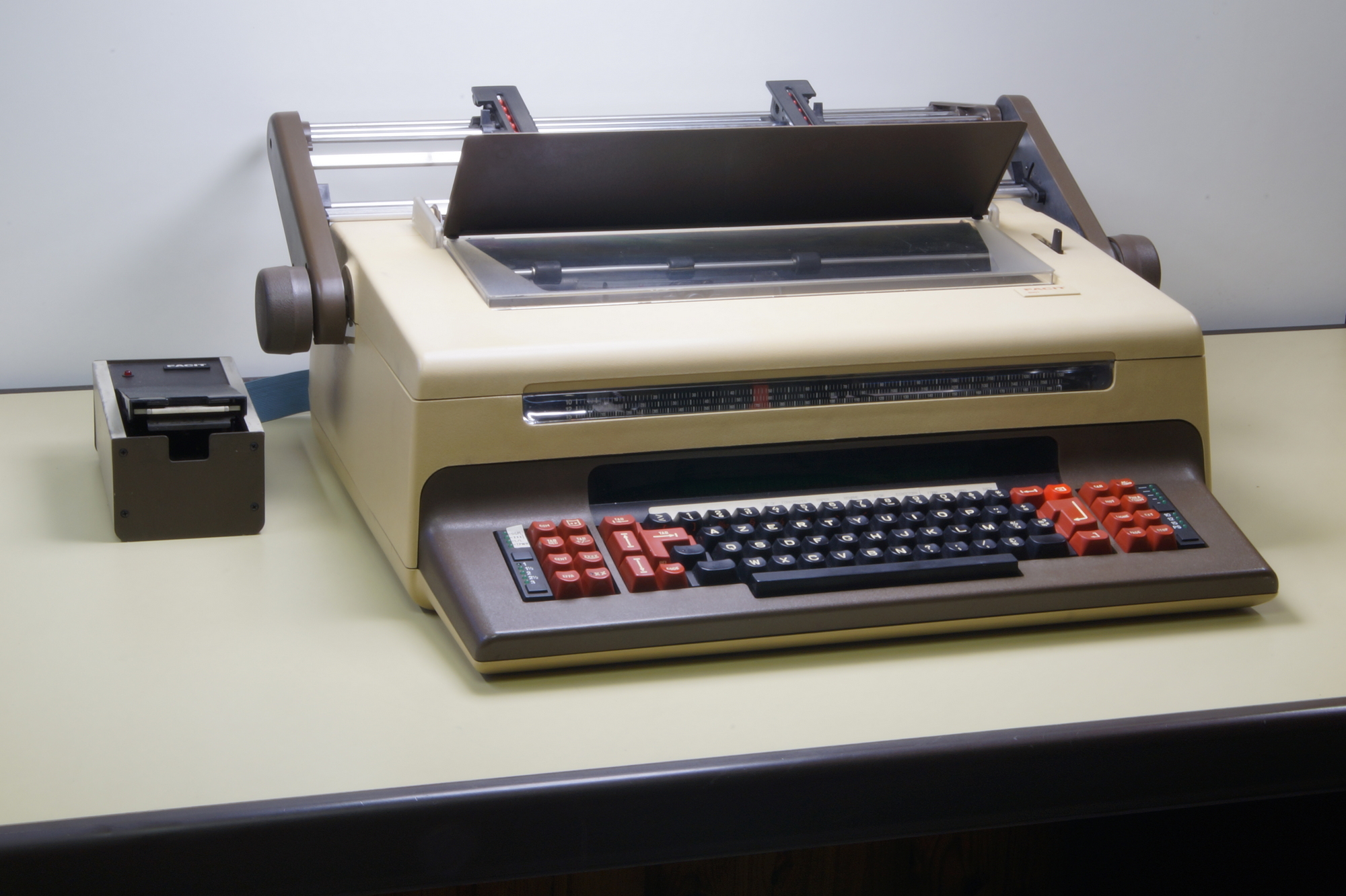
That’s how it looks now, but not one month ago, I just put it in 2002 in a plastic bag, not cleaned after using it for 5 years as printer. More, the foam used as sound absorber inside de covers and on the mechanical frame was falling as dust when touched.
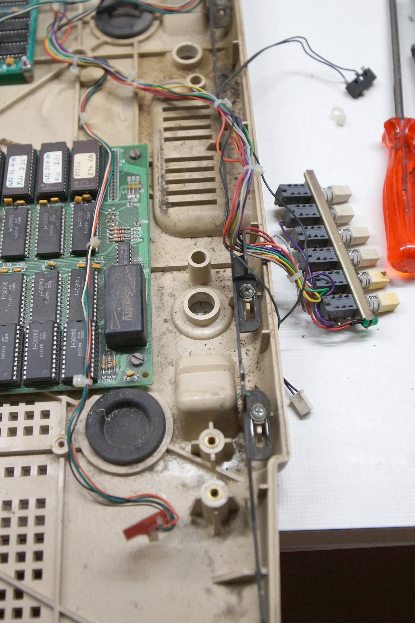
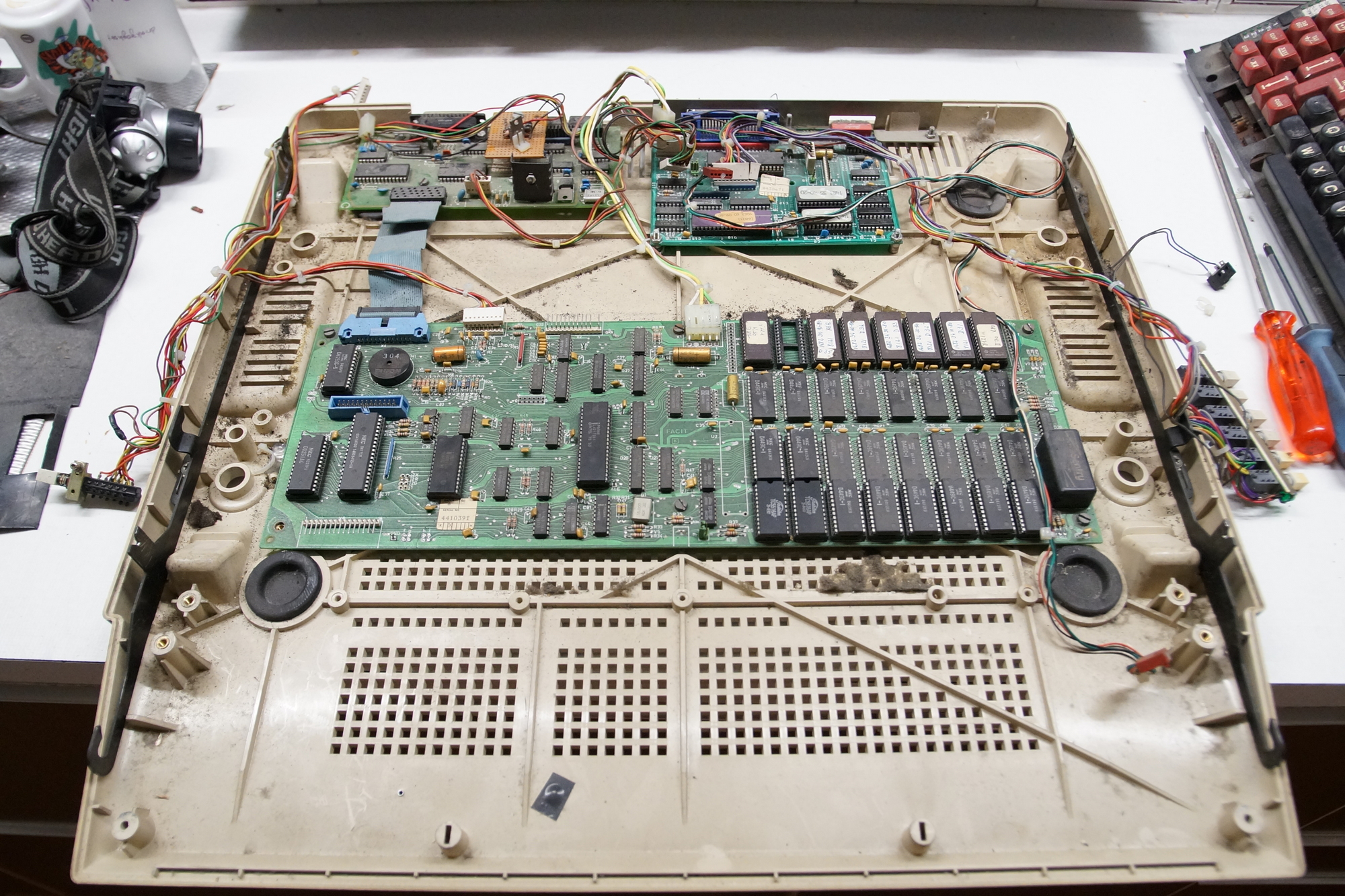
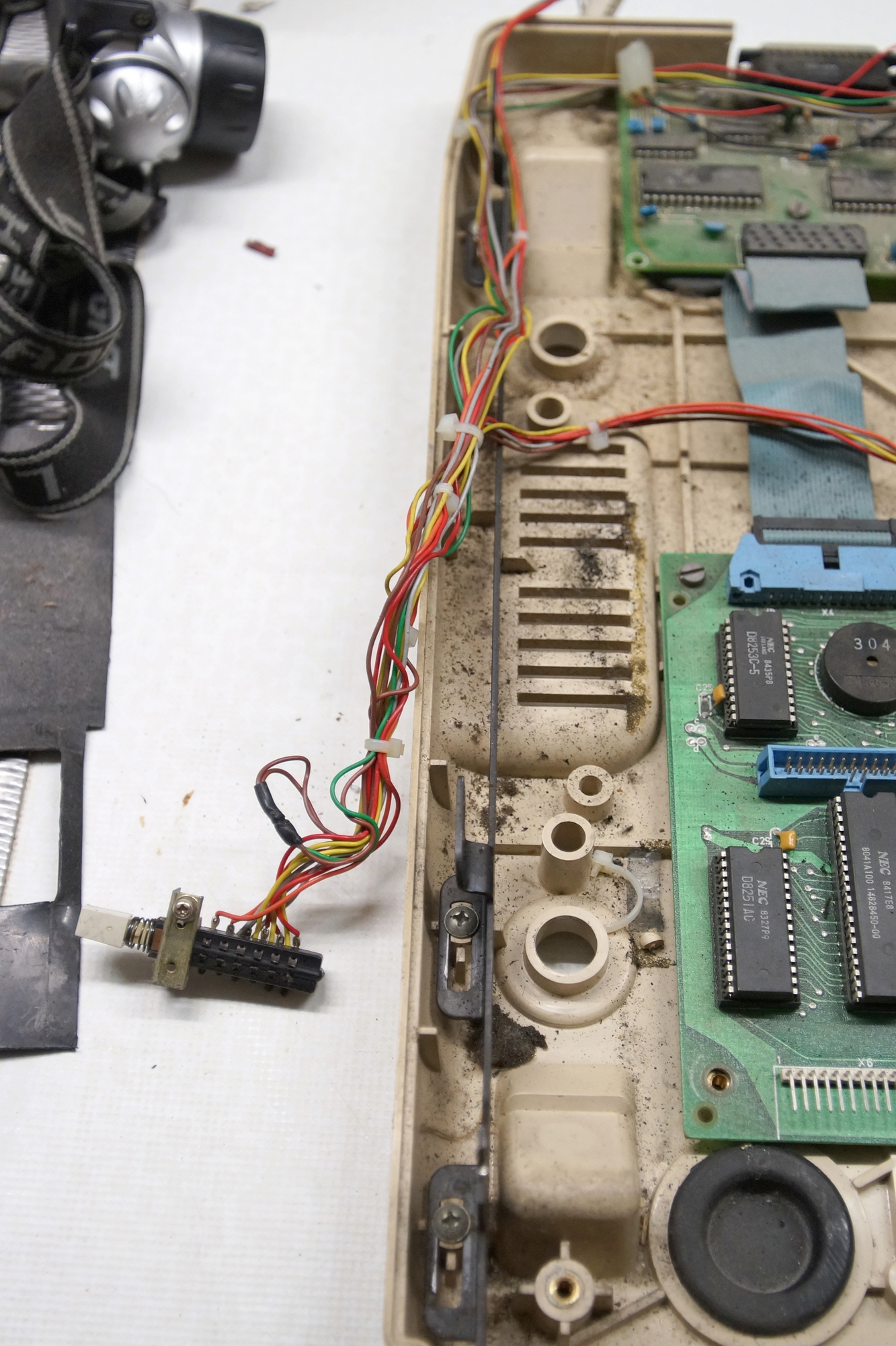
A few pics at the beginning from the bottom cover to remember me the wiring modifications I made 30 years ago.
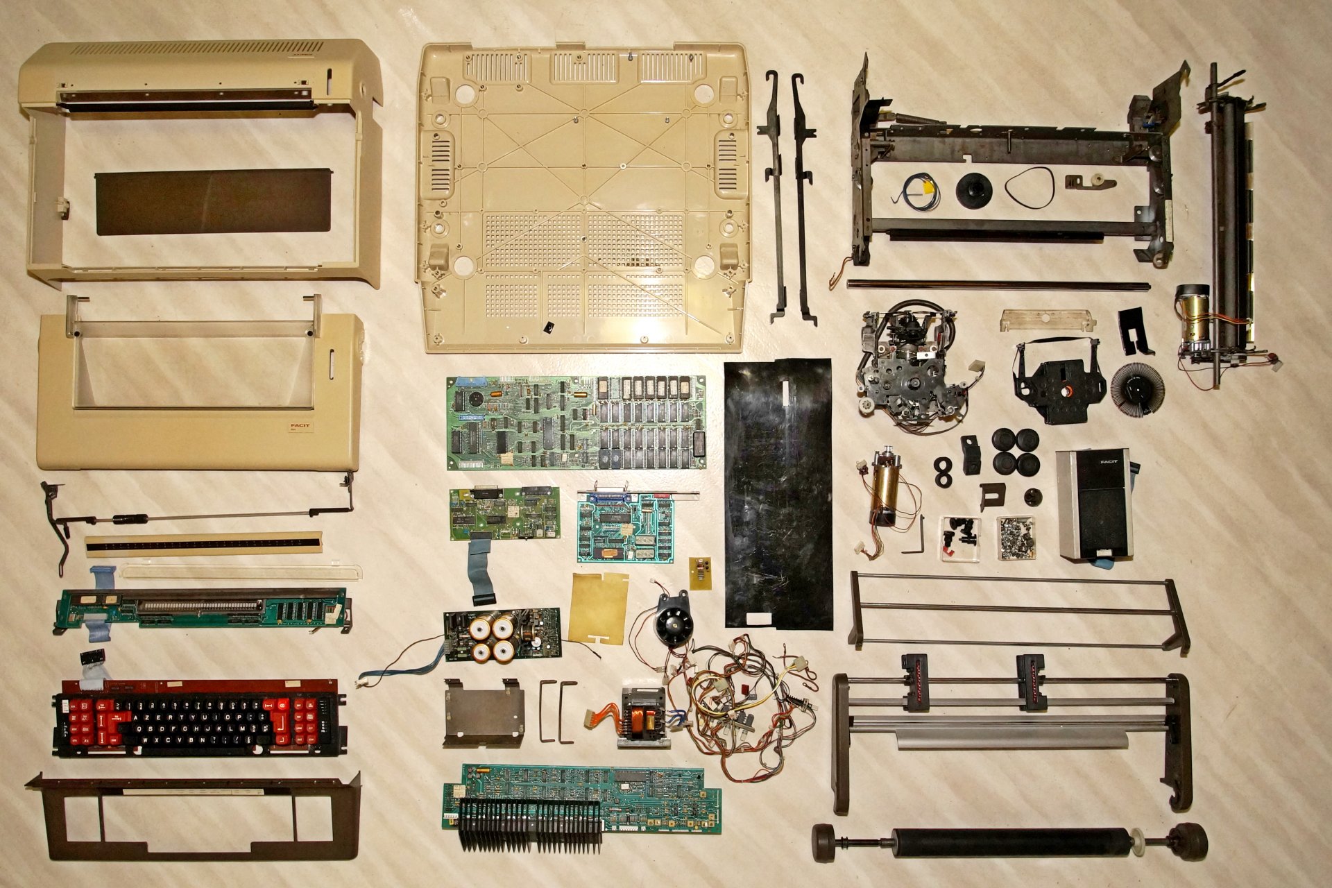
Now, it’s cleaned !
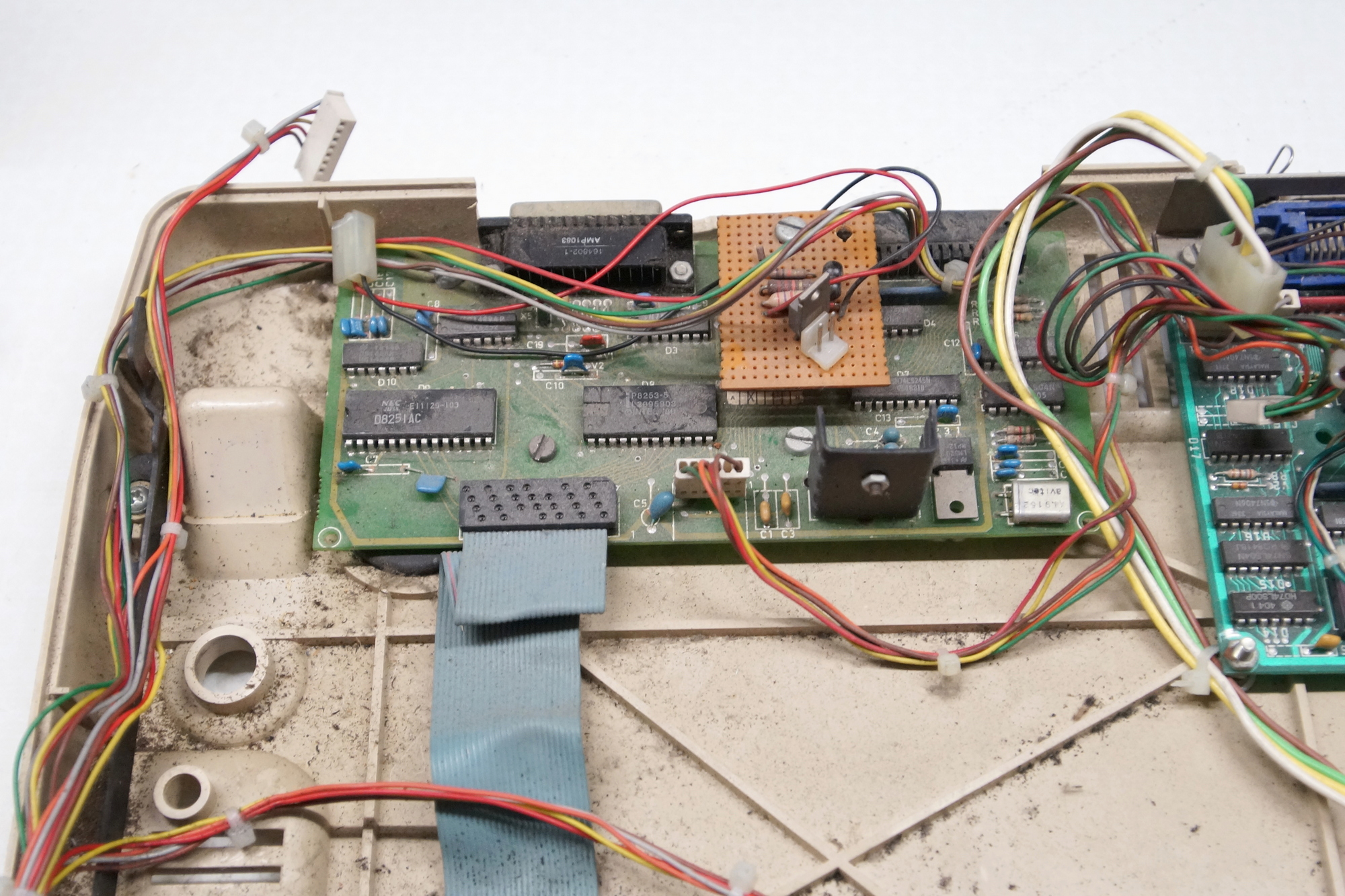
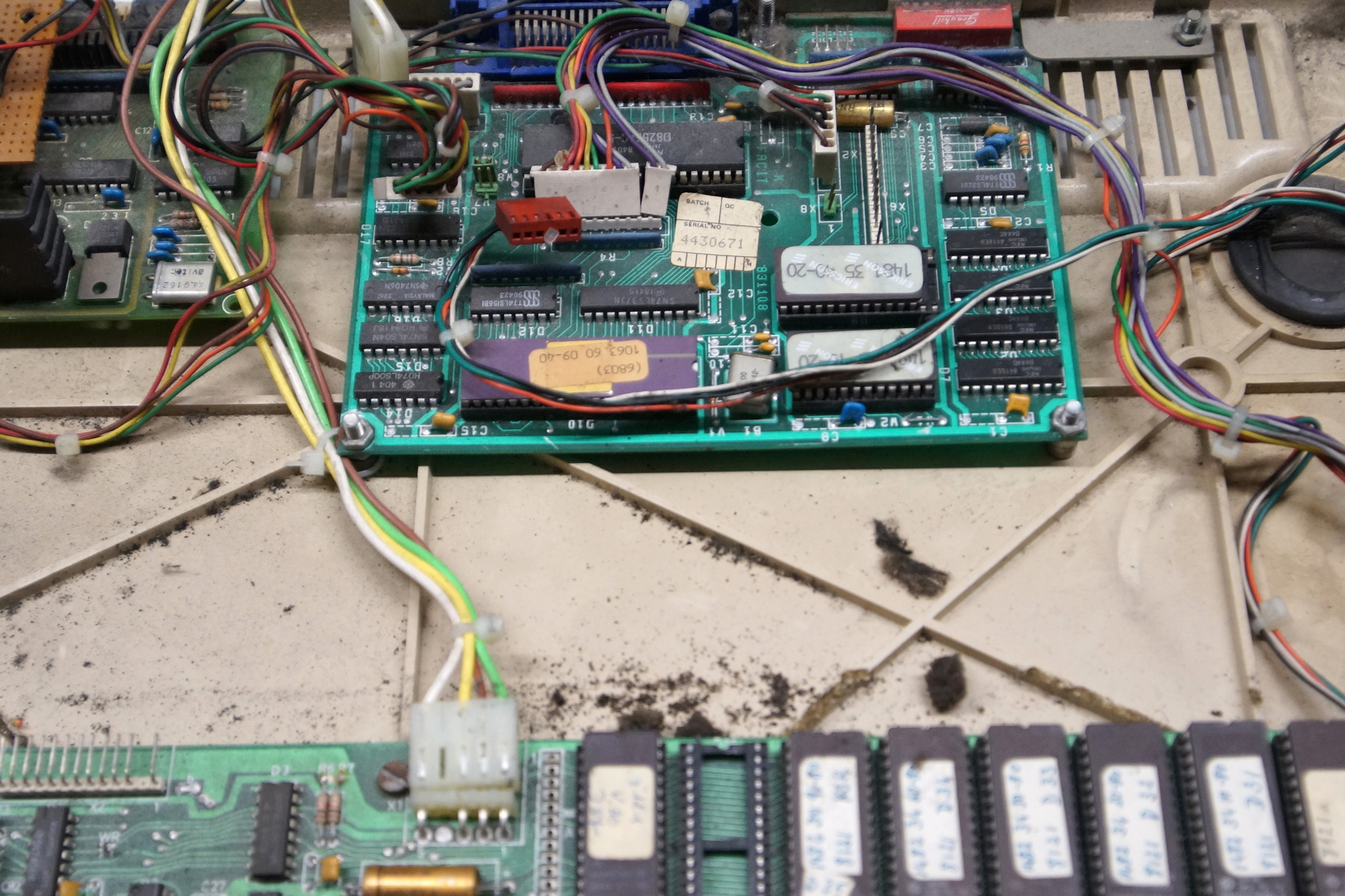
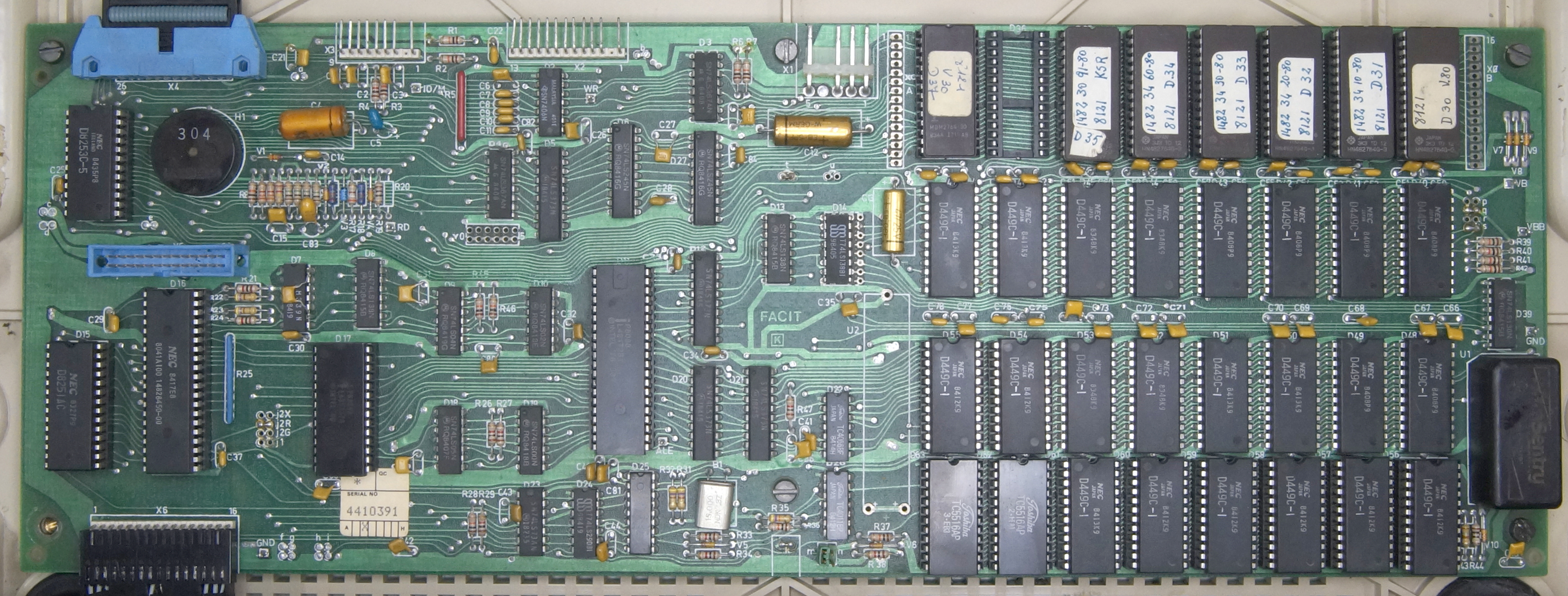
The CPU board Facit 8121, microprocessor 8088, 7 EPROM’s 2764 8Kx8 for the program and 24 Static RAM 2Kx8 Toshiba TC5516 or NEC µPD449.
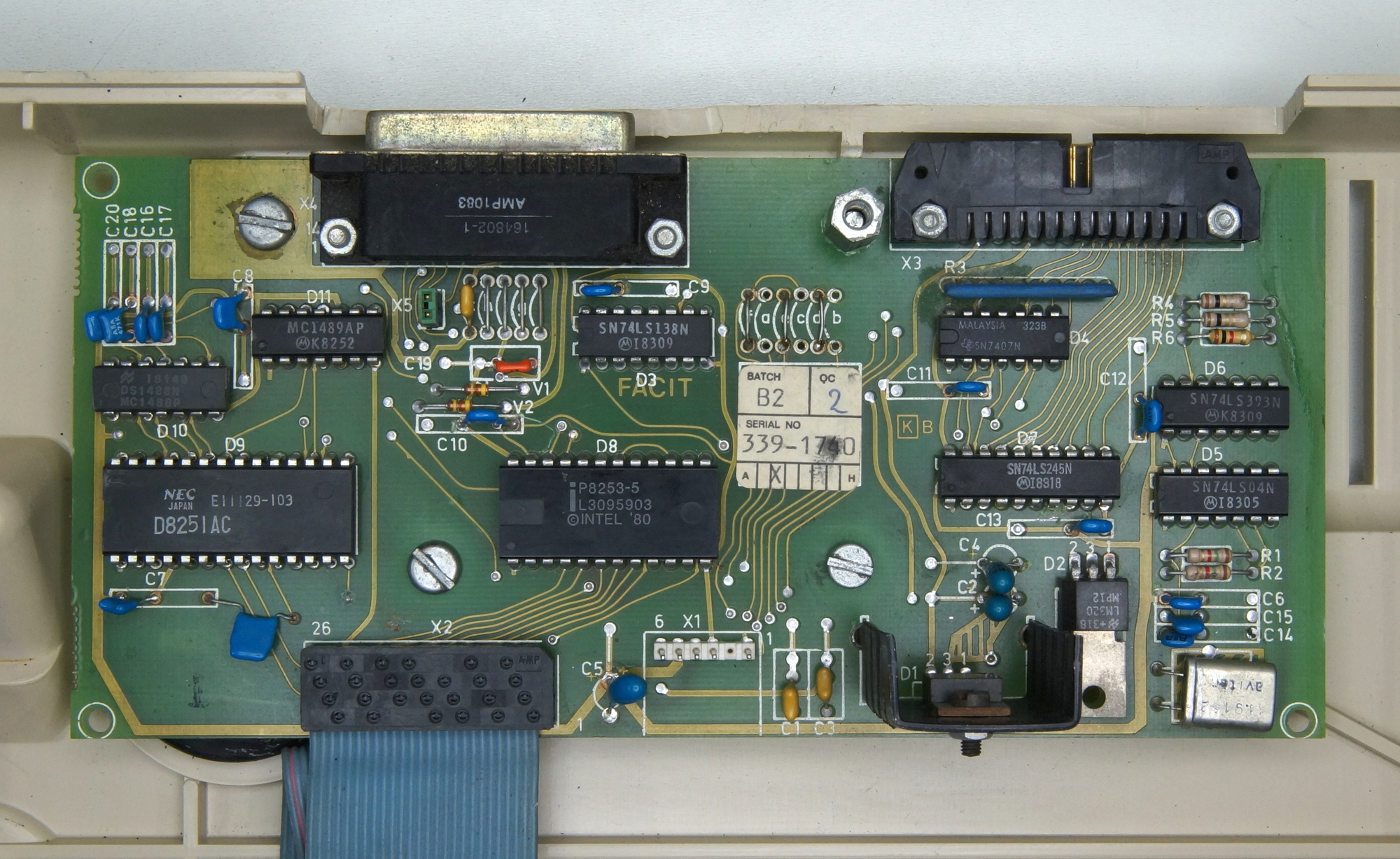
The serial interface RS232 (or V24) combined with the micro-floppy interface was an option, FACIT add then KSR for Keyboard Send & Receive to the model name. (see EPROM D35)
Can be used to receive data to print and/or to send data to a mainframe or even to another TPWR. As terminal, can be configured in full duplex, the characters typed on the keyboard are only sent to the other device, or in half duplex, the characters are then sent to the other device AND reinjected by the UART in the receive buffer to print a local copy at the same time.
Standard was the TPWR sold with only the small micro-floppy interface as the one in the Haata’s Flickr Album https://www.flickr.com/photos/triplehaa ... 0265552743 middle of page two.
Now with the Cooling fan driver I quickly made to replace the one on prototype board. The cooling fan was installed on the printer-only of the same series, the 4560.
The parallel interface (or Centronics) was not an option but was used on a basic model 7900 or 8001 as receive only cheaper printer option.
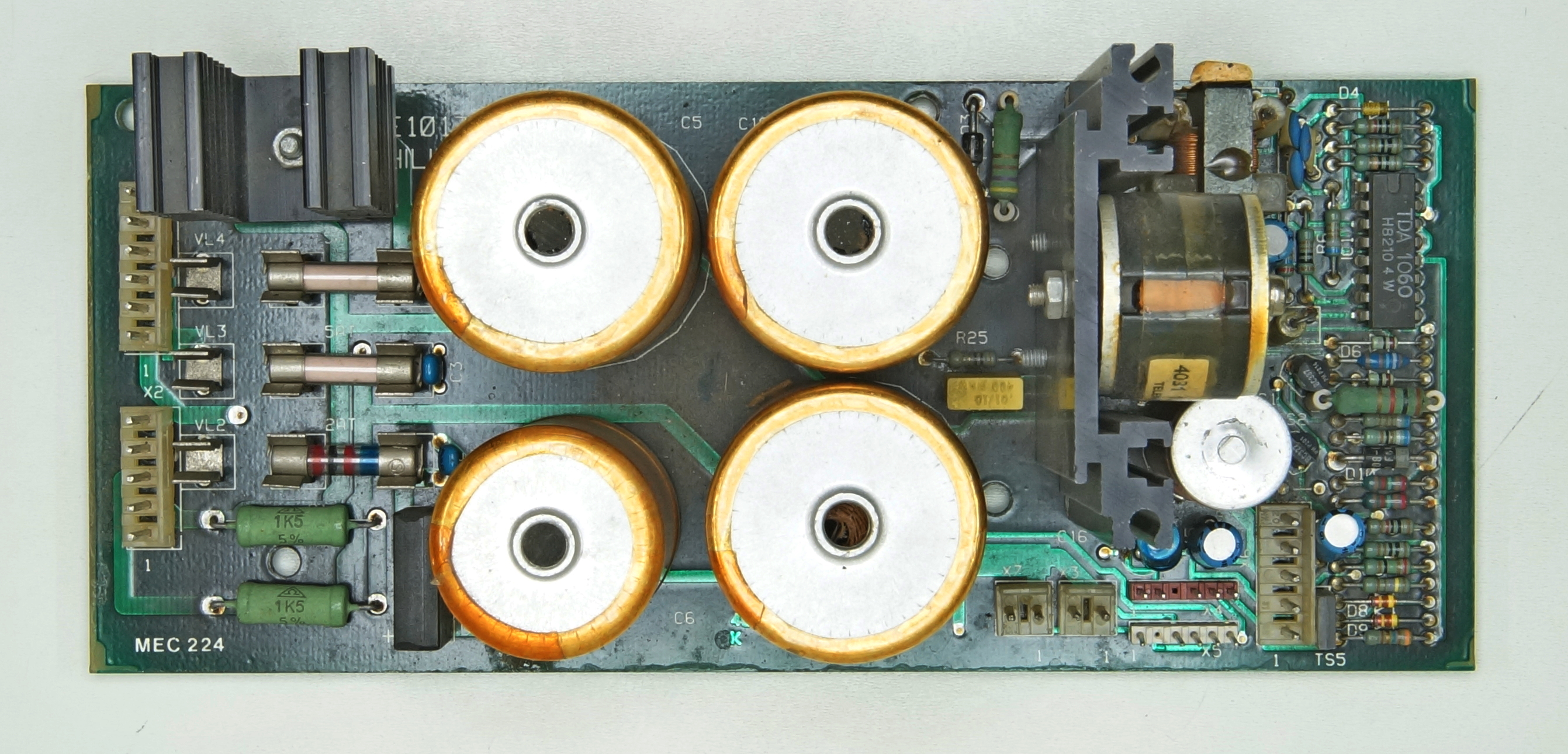
The power supply, a little more power than the 8111 or 6480 to also drive the dual bin cut sheet feeder option.
The control board, the driver for the 4 motors, the hammer and more.
The bottom plate almost complete.
The cleaning of the ribbon feed.
The driving parts.
Now, just to reassemble
The ribbon feed, top view.
Bottom view
The carriage complete.
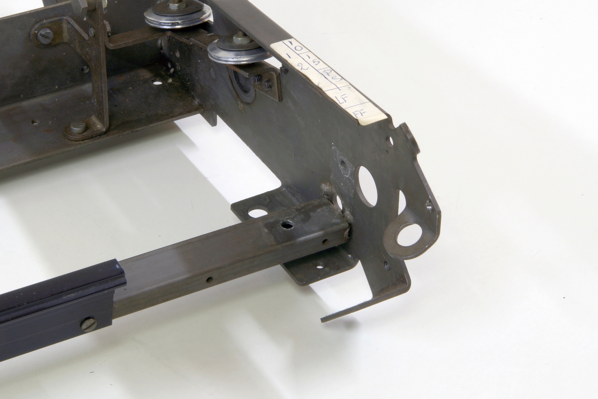
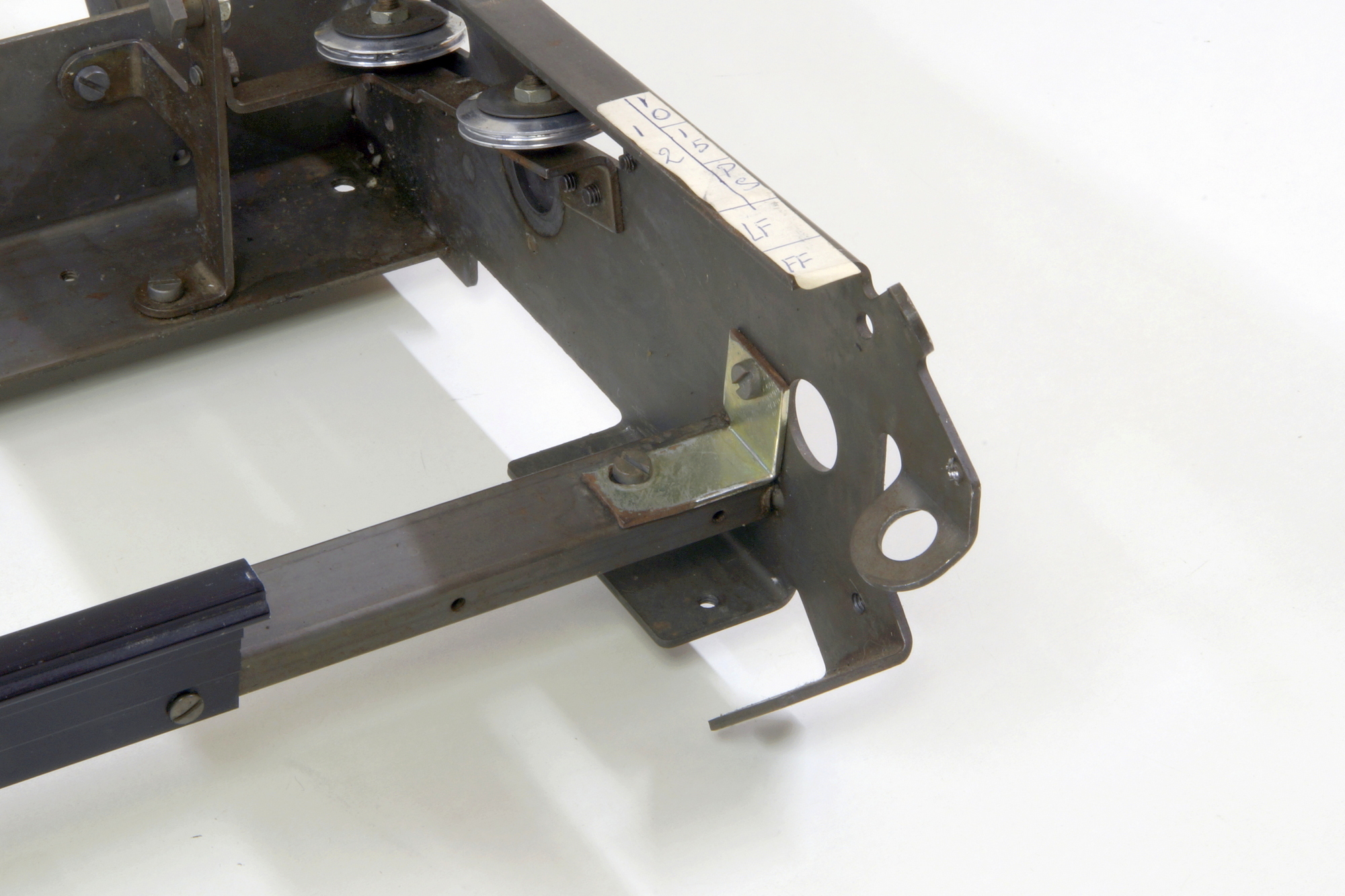
The frame
At the right-hand side, you can see why this machine was taken out the stock, I could use it as spare parts but preferred a quick (ugly too, I agree) repair and use it as test machine to repair the electronic boards replaced in the field or by our local resellers.
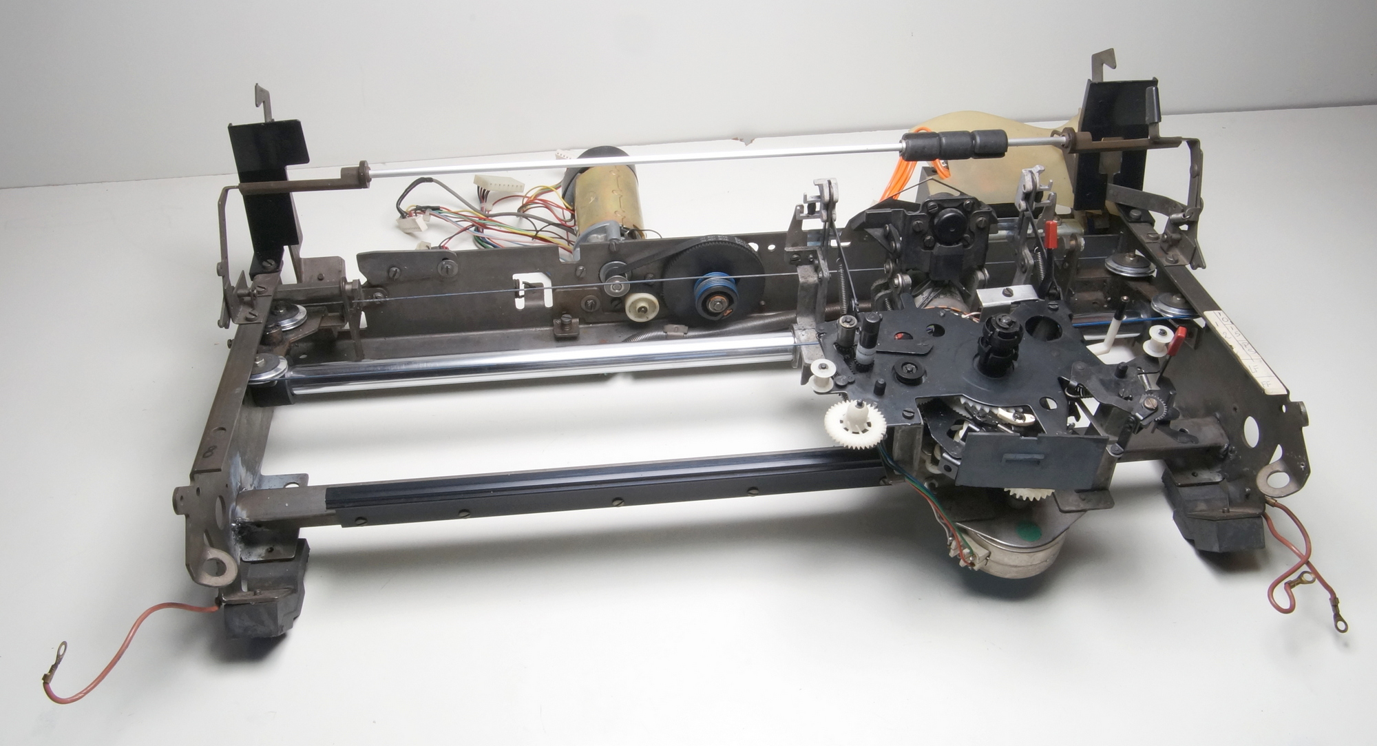
It should look like this.
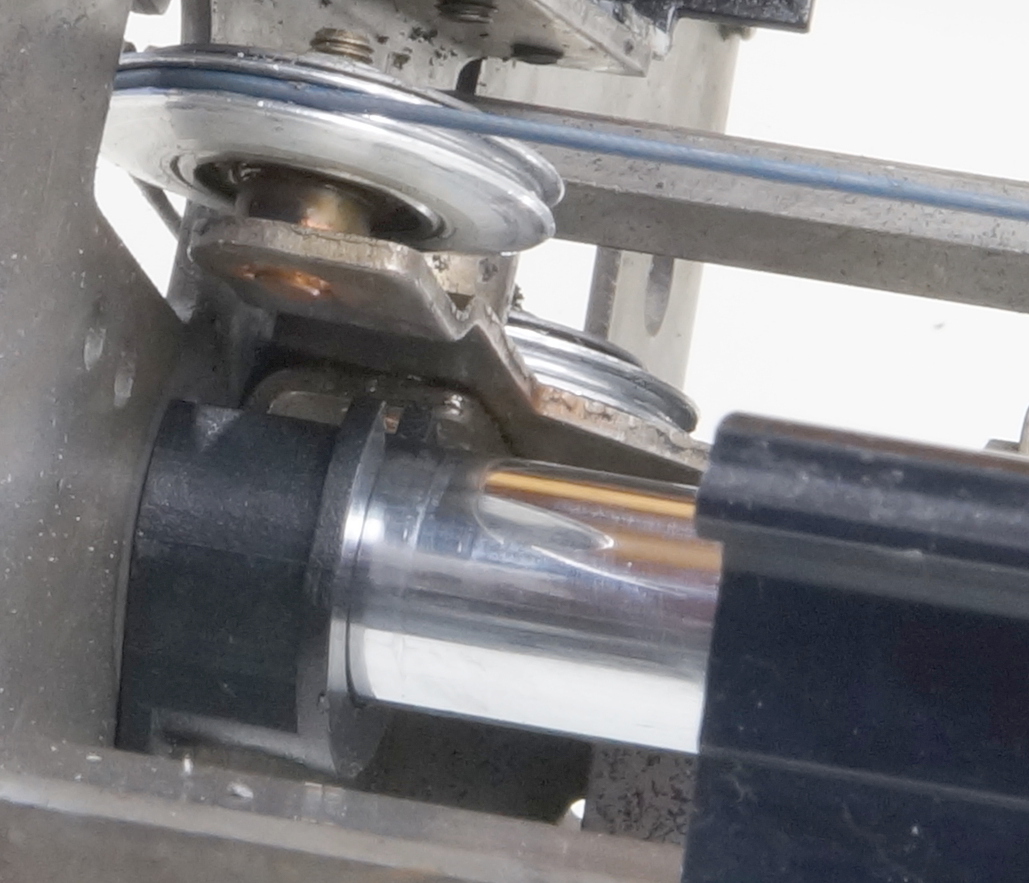
The carriage, the carriage motor with the drive pulley, the belt and the wires, and the transformer back in place.
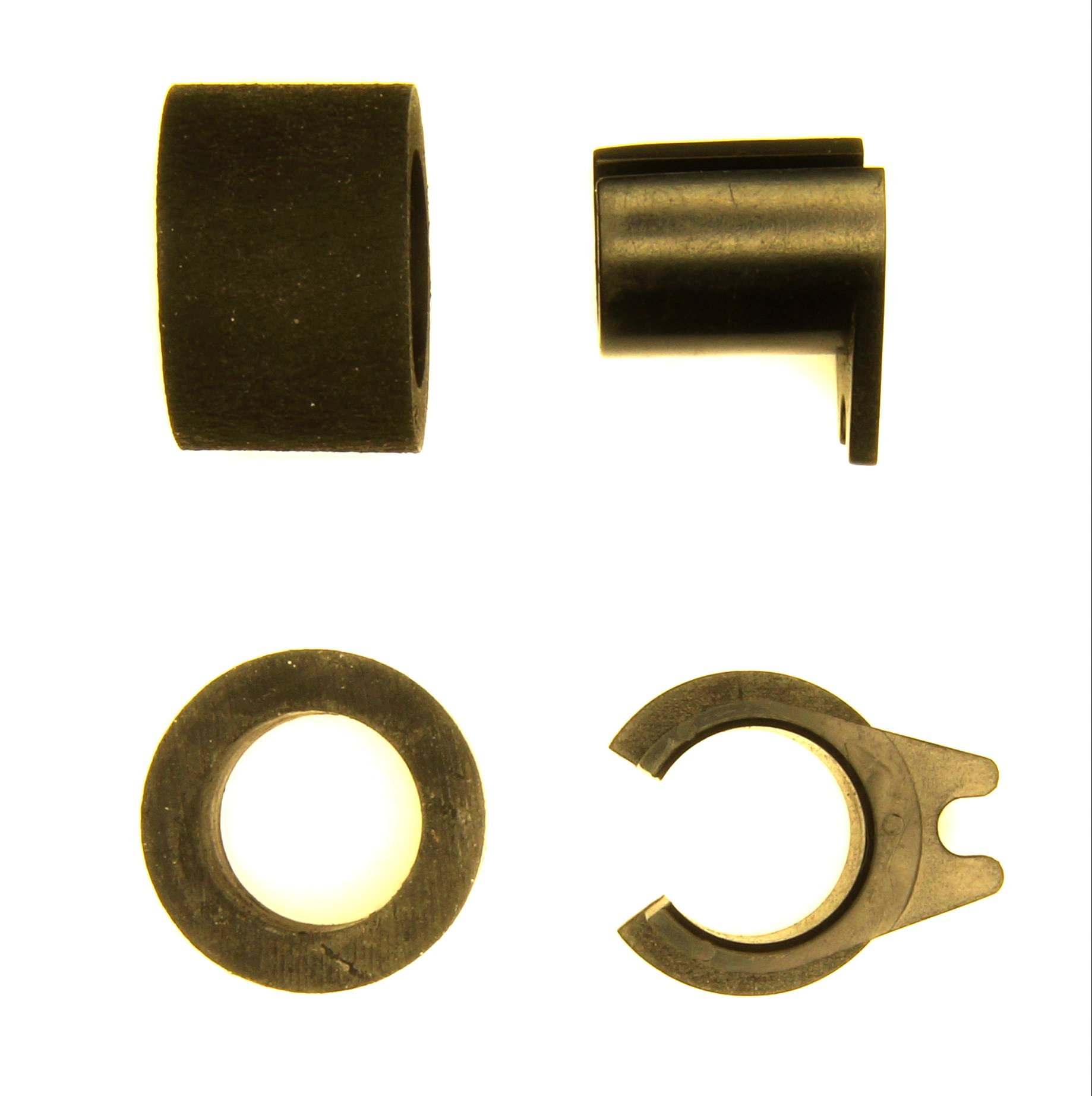
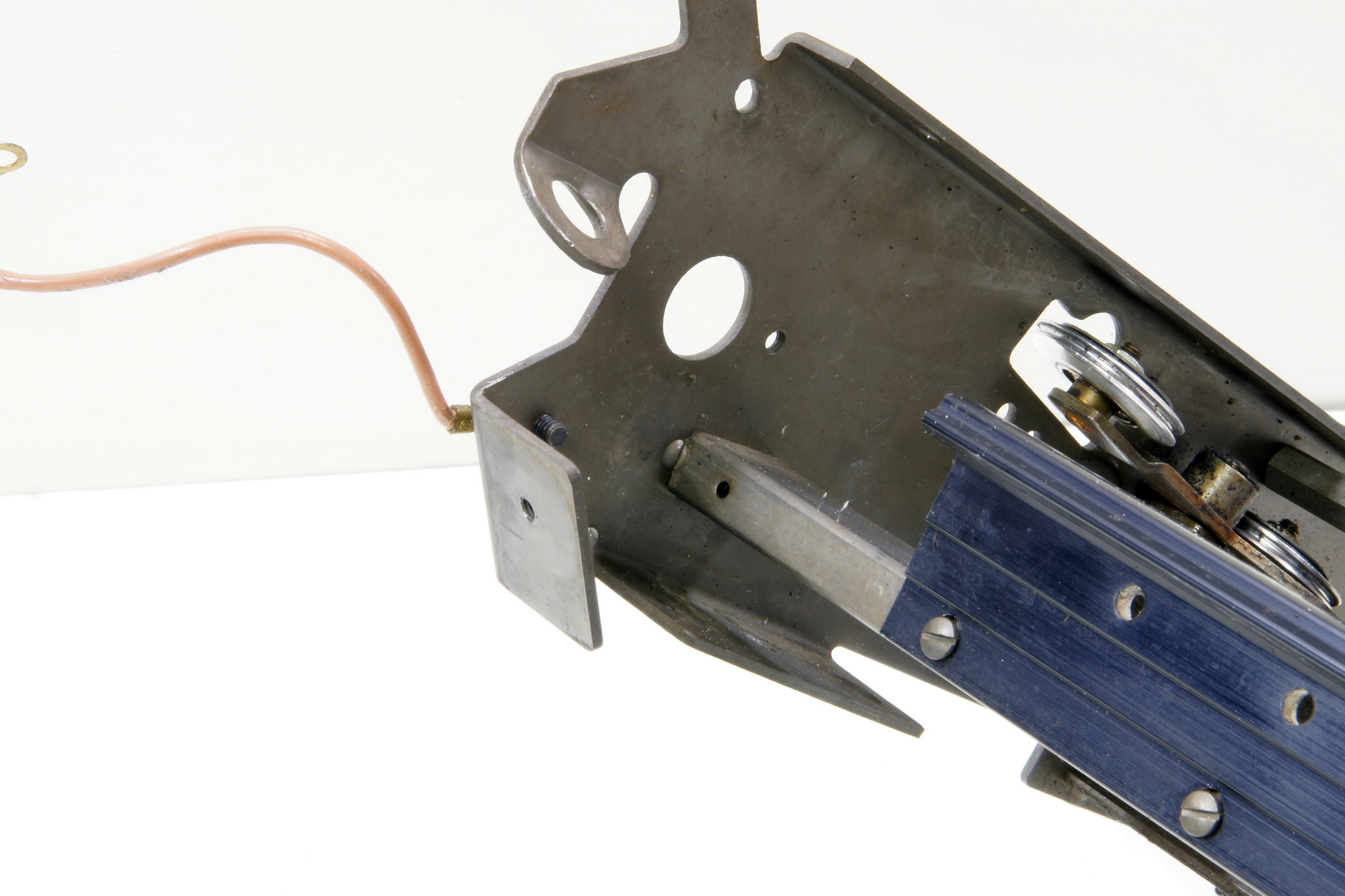
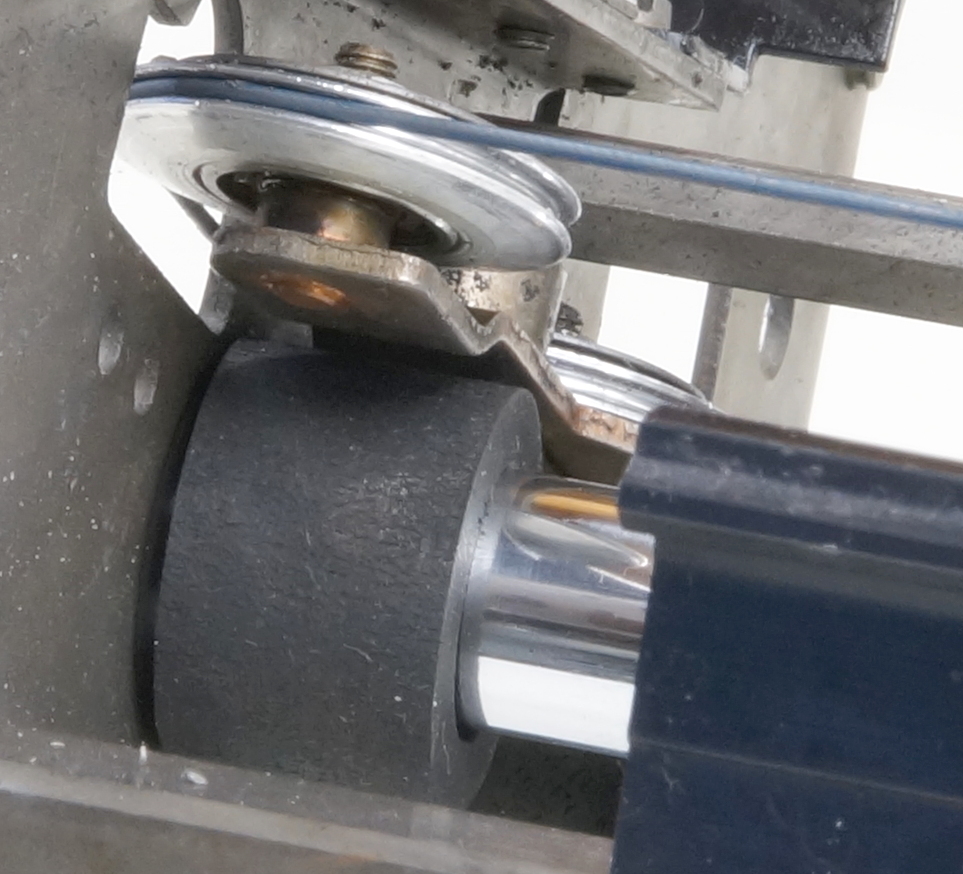
A little bit too fast, these rubber carriage stops are inflating when the rails are lubricated, a newer ABS model was made.
The new one.
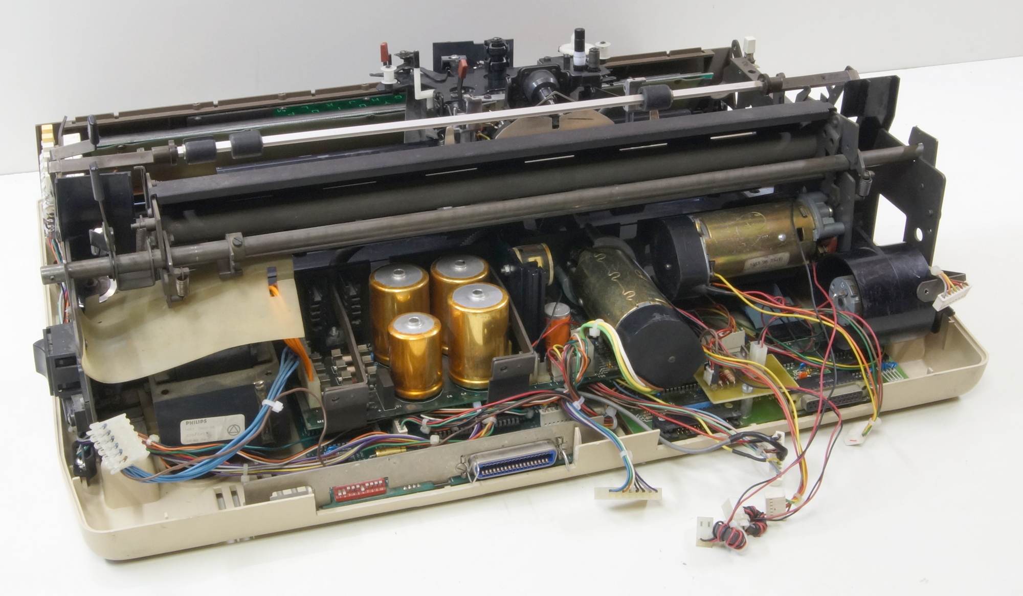
With the power supply back in place.
The frame back on the bottom plate, front view.
Back view without control board.
With the control board.
Ready to switch the power ON.
But first, the cleaning the test box and drawing a new label with the trimpots and their adjustment values. The box is used to start the test program and adjust the speed of the motors (tachometer/velocity), also the shape and voltage of the signals (position) coming out the optical sensors and to adjust the position of the ribbon stepper motor on the right step.
The test program is running, you can see the carriage moving and the print wheel turning.
The preceding was with the original MicroController Motorola MC6801, here is with my own build MyController …
I made this to repair the control boards. Every output port of the microcontroller has his own dip-switch, the inputs one LED. I could check each step of the analogic speed (15) and direction for the printwheel and platen motors and the carriage motor (31). Also drive the stepper motor for the ribbon step by step (4) and adjust the current (4). Also included an adjustable pulse generator for the hammer.
The optical sensors of the 3 DC motors and the ribbon end are monitored by LED’s.
Here is the printwheel turning at velocity 13 and the platen motor is locked, the carriage motor should be moving at velocity 3 but I disconnected it for a steady photo.
Here is the printwheel motor locked and the platen motor turning at velocity 1.
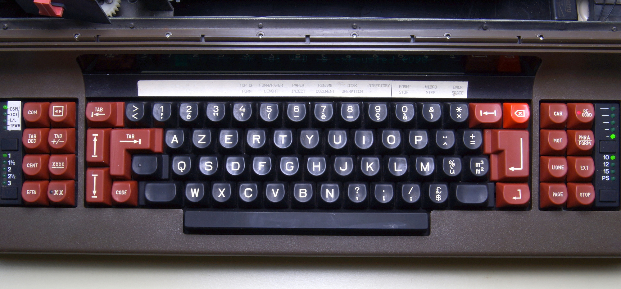
This is The Belgian keyboard layout.
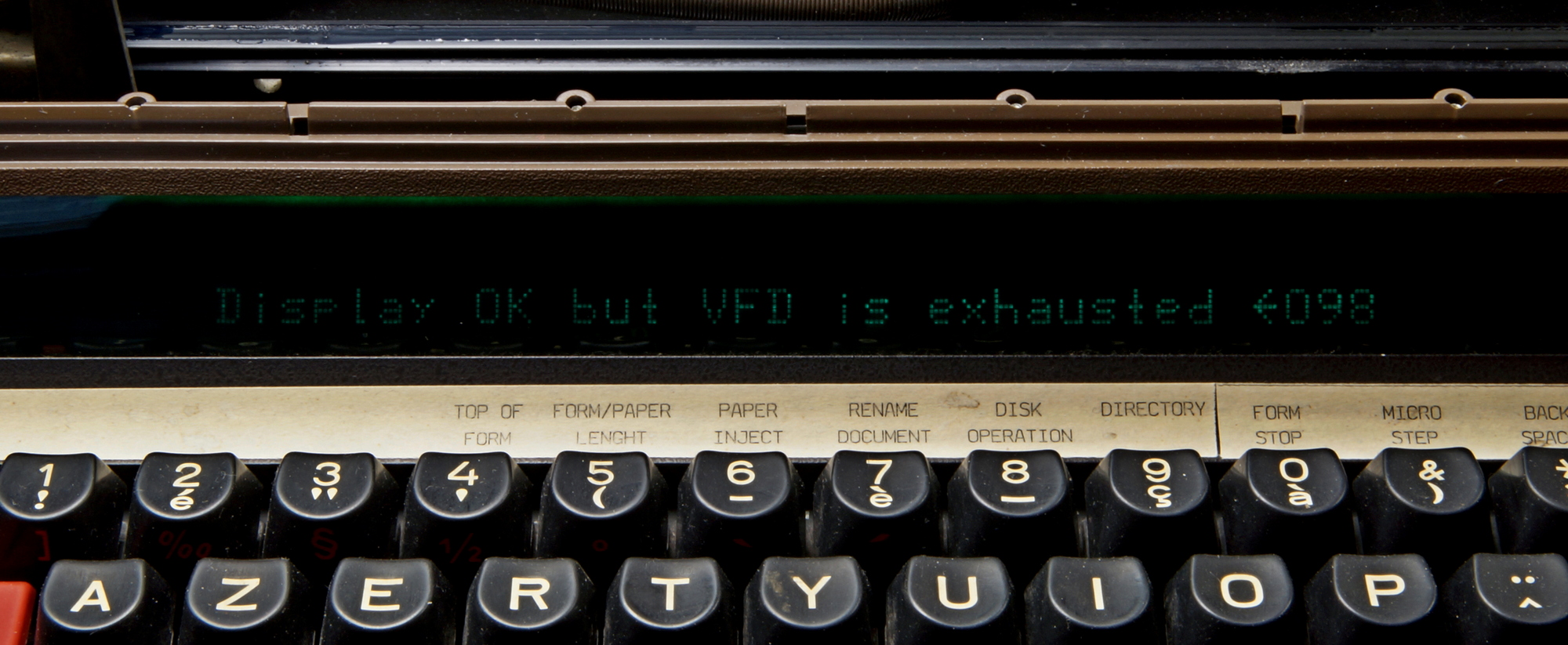
The display should be replaced, I found only one, on eBay in the US, a little bit expensive, 65$ + 31$ shipping + customs.
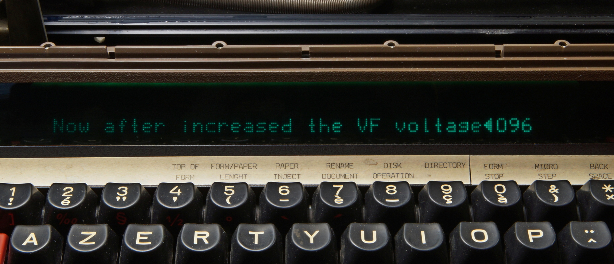
After boosting the filament voltage a few volts.
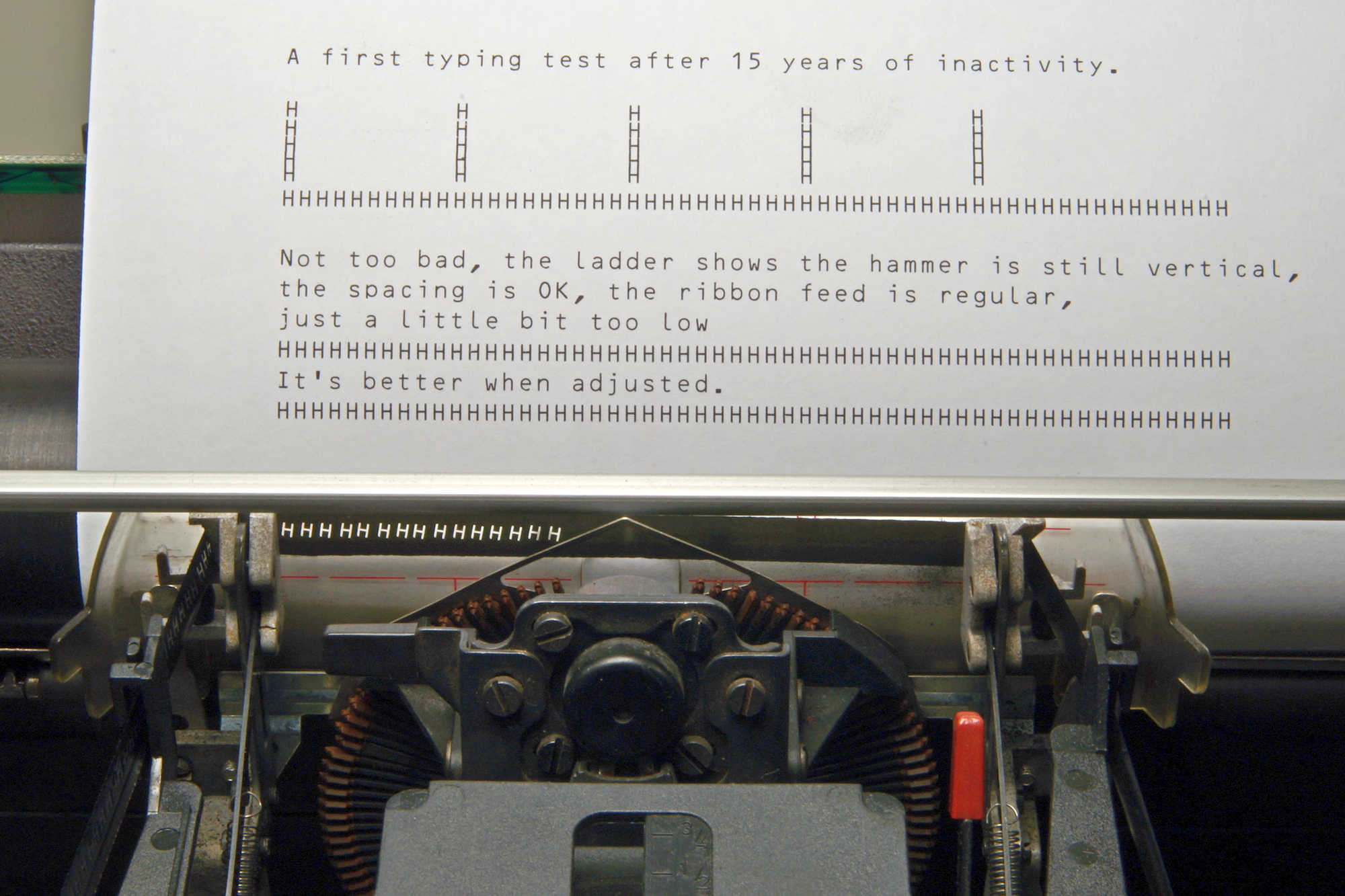
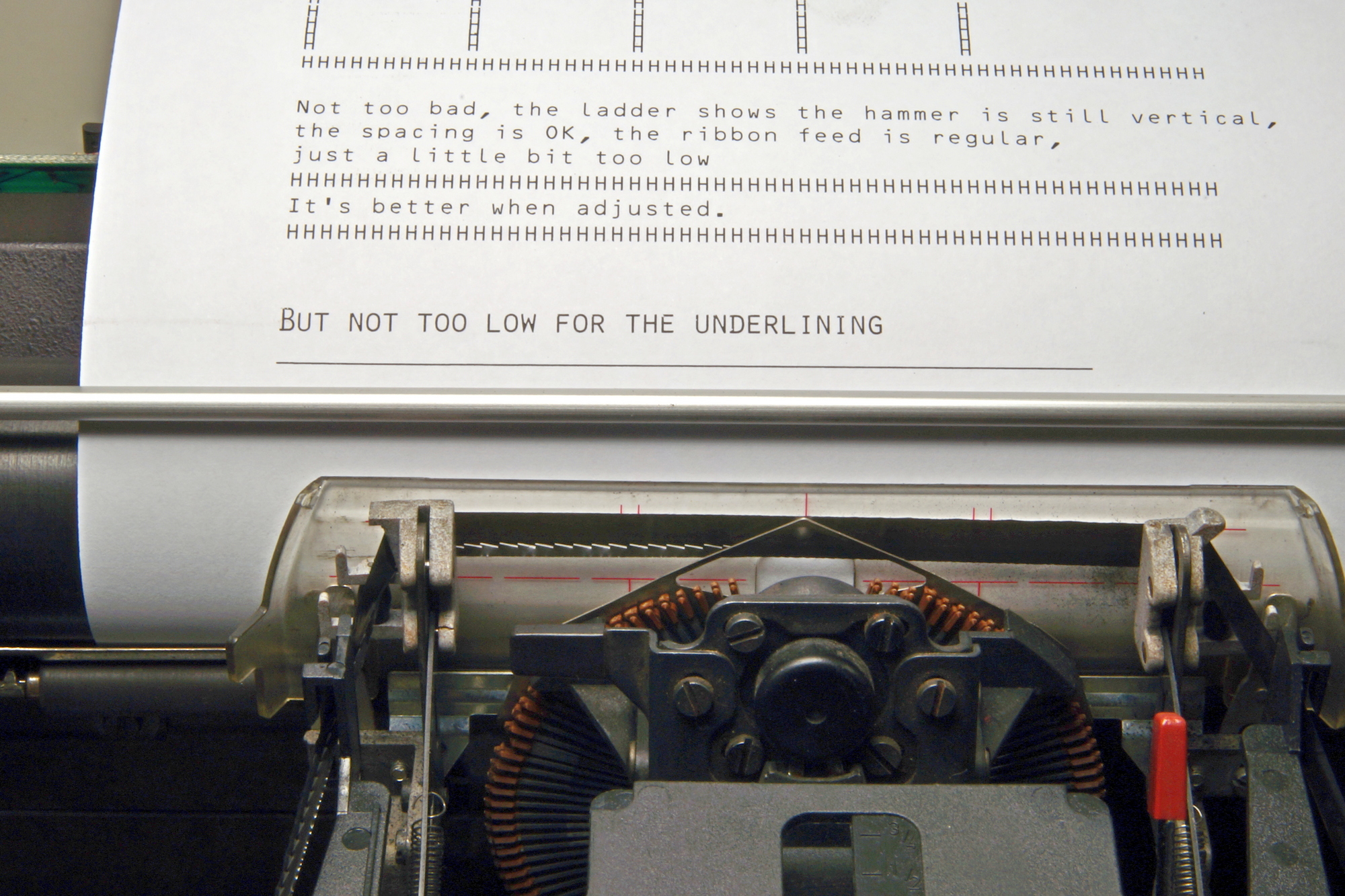
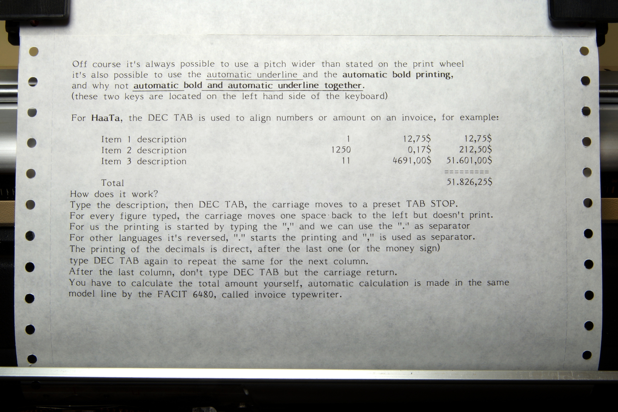
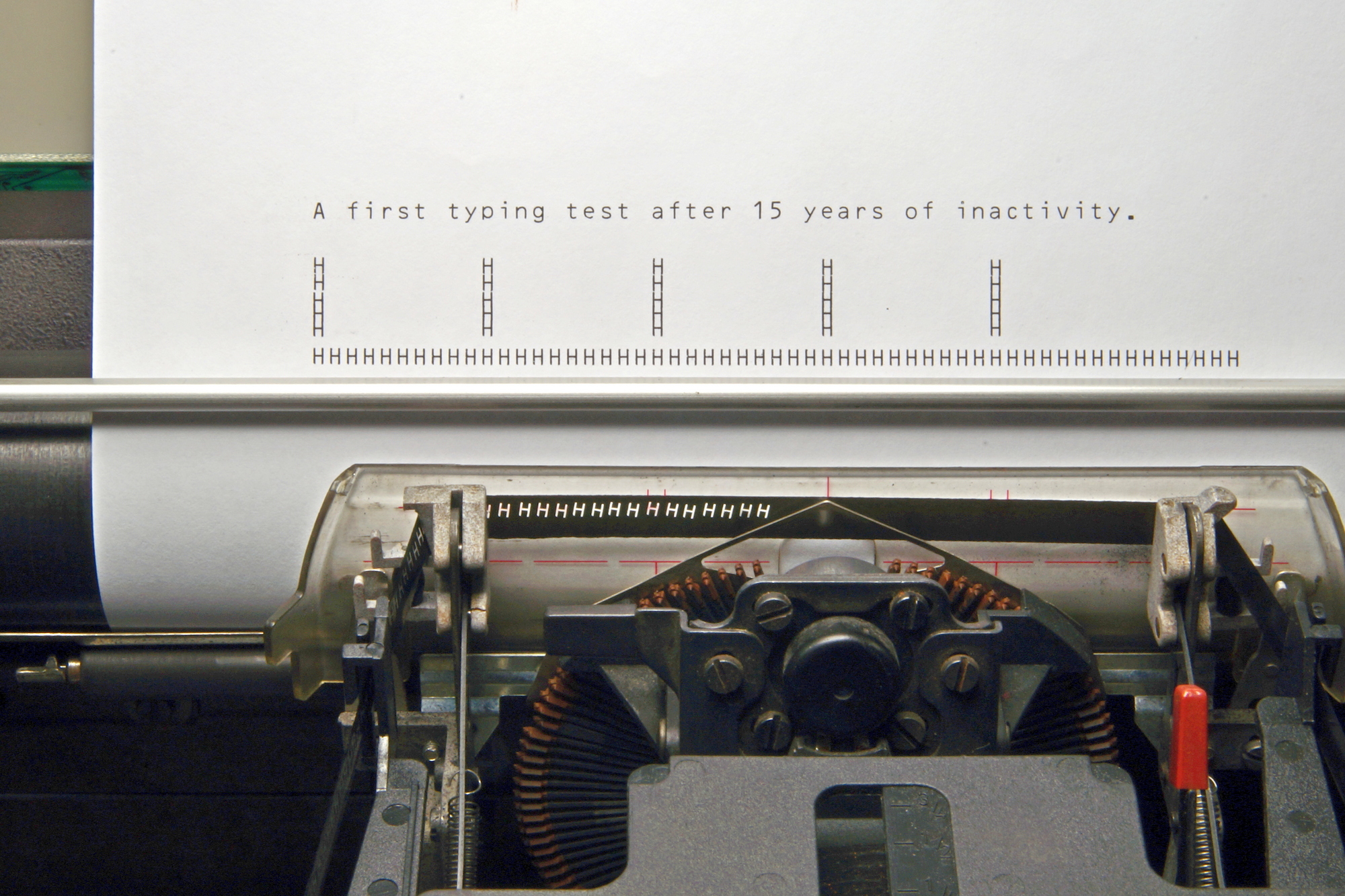
Now the printing tests.
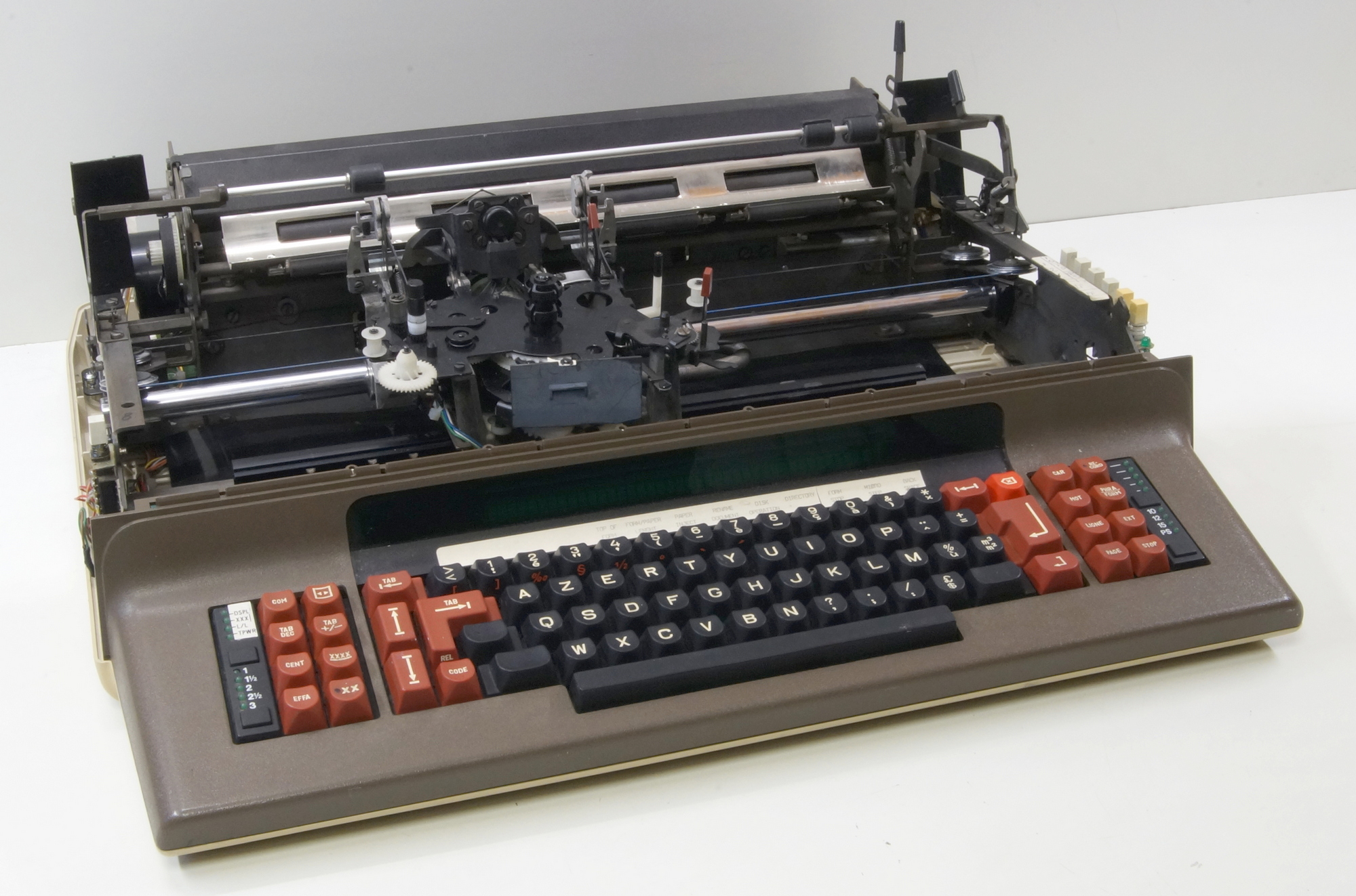
Rebuilt with covers.
These knobs are missing on Haata’s TPWR !
Another option the Tractor Feed also called Pin Feed, with longer knobs shafts.
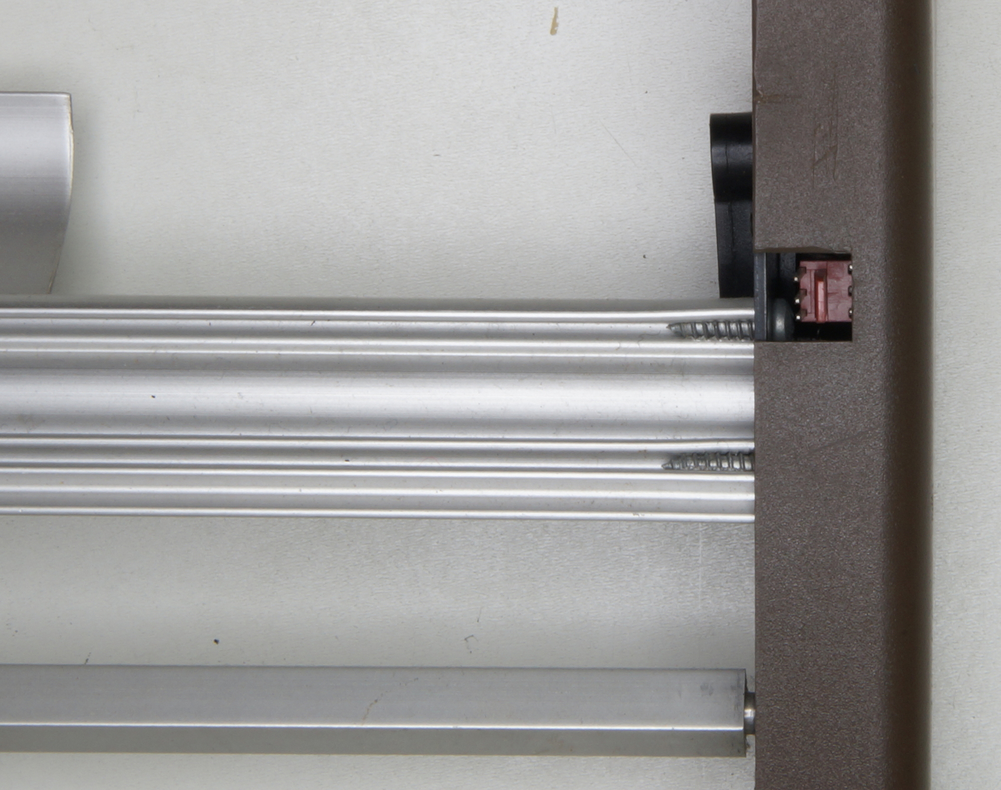
One cable is missing, the paper end sensor connected under the right cover.
With standard knobs.
With tractor feed knobs.
Tractor feed installed.
With paper holders open, ready to feed the paper.
Paper in place, paper holders closed but holders unlocked, and paper end bail locked up.
The paper can now be moved left or right to adjust the printing position.
Now, the paper holders are locked, and the paper end bail is lowered, tensioning the paper.
As printer, the right position was the left side, WYSIWYG was almost unknown then. Sending a margin was possible but reducing the number of printable characters. The standard was 8 inches, pitch 10 = 80 characters per line.
As TPWR, no problem, just use the space to the first printing position and press the margin knob (here is only one knob, the right margin is Code+Margin, on the right of the COM knob).
A double bin cut sheet feed was also as option, with electronic control and DC motor paper feed.
The print wheel in its box.
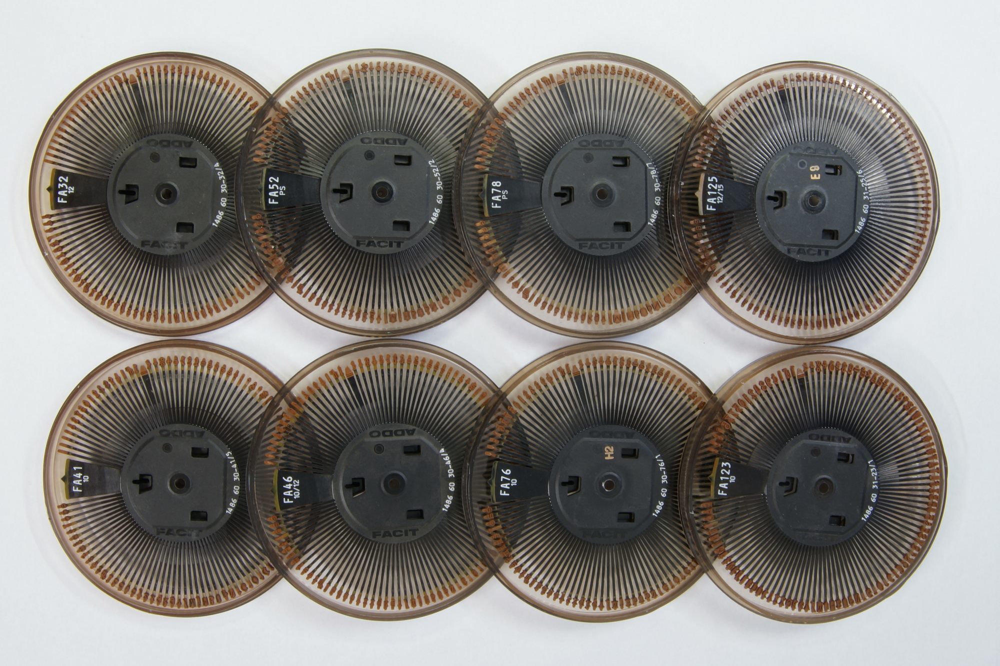
Several type styles with the reference FAxxx (FA for Facit-Addo).
46 with recommended pitch 10 or 12 (80 or 96 characters on an 8-inch-wide paper).
52 with pitch PS = Proportional spacing, the number of micro-steps spacing is depending of the character. Look at the difference between o, a e and m and w.
8 character styles.
4 more ! How many fonts do you really use on your computer ???
2 printwheels 46, the right one was the original, later, they replaced the upper part by 7 extra characters, making a printwheel with 112 characters in place of 105.
This was the beginning, only one new character is added, | making possible to draw a vertical line or in conjunction with the underline, a box without interruption.
This one has already 112 characters, it’s a German language ! see the 6th character .
Two prinwheels 123, on the left, 603 for the French language, on the right 604 for the English language, find the differences.
The different printing styles.
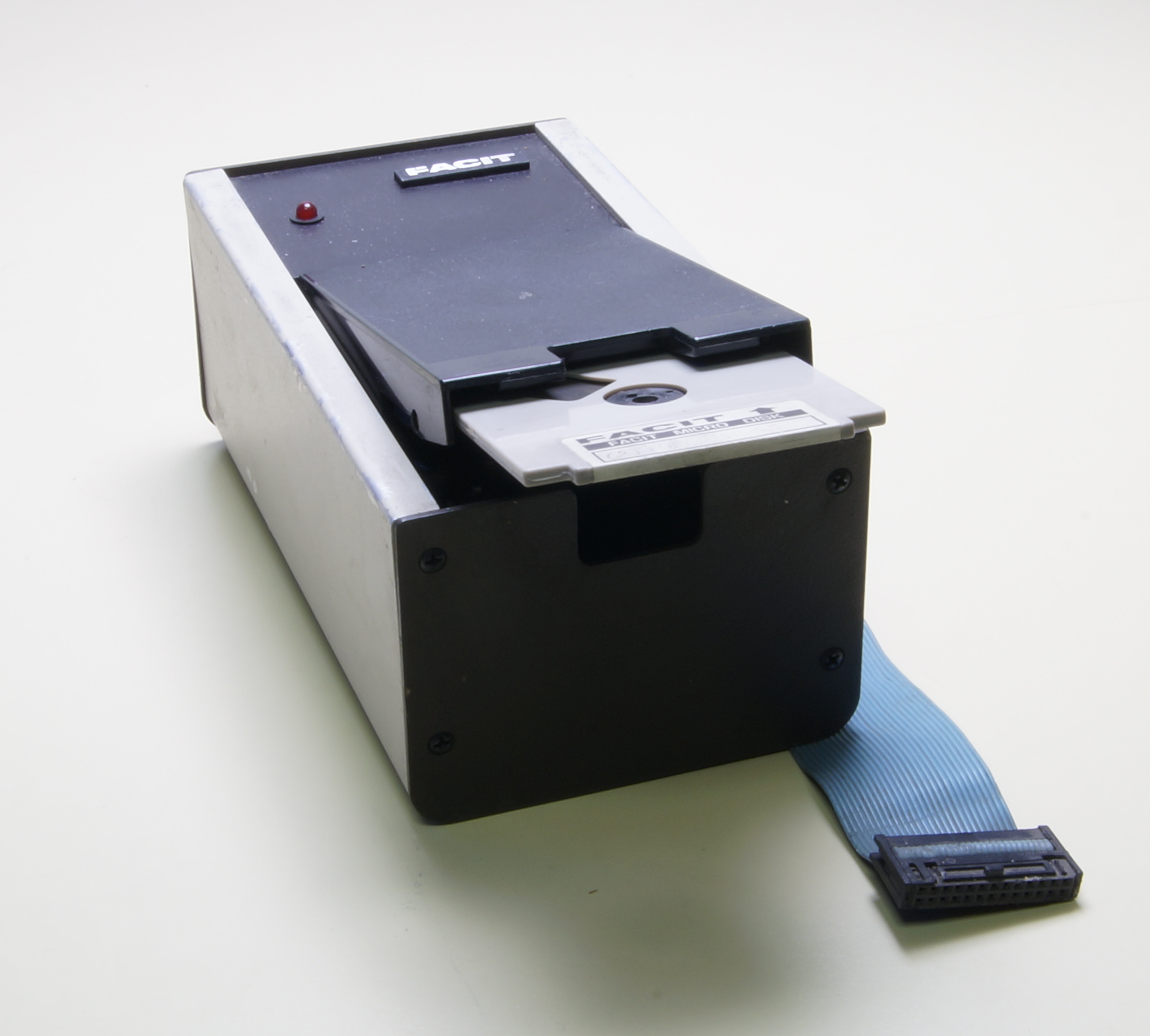
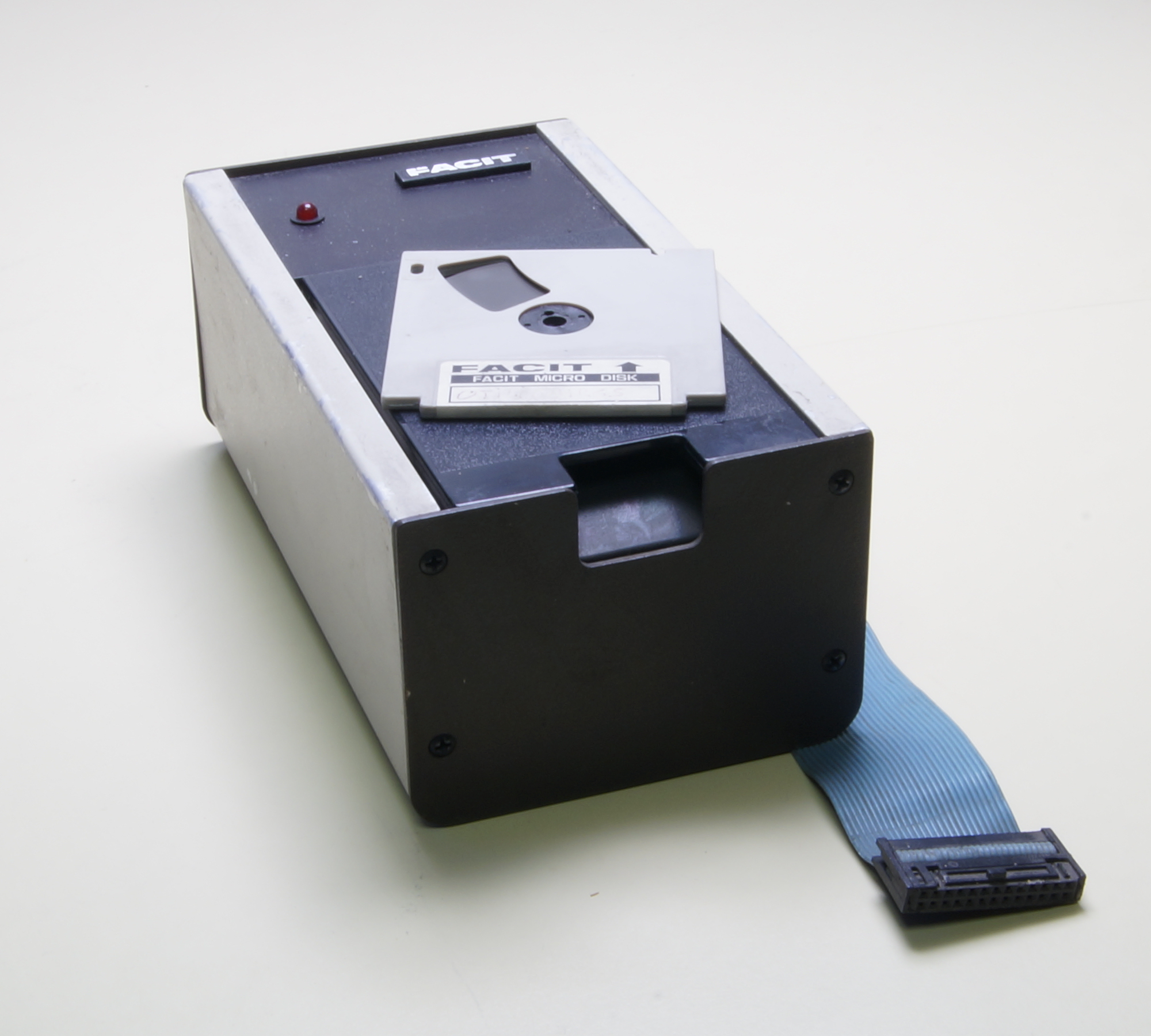
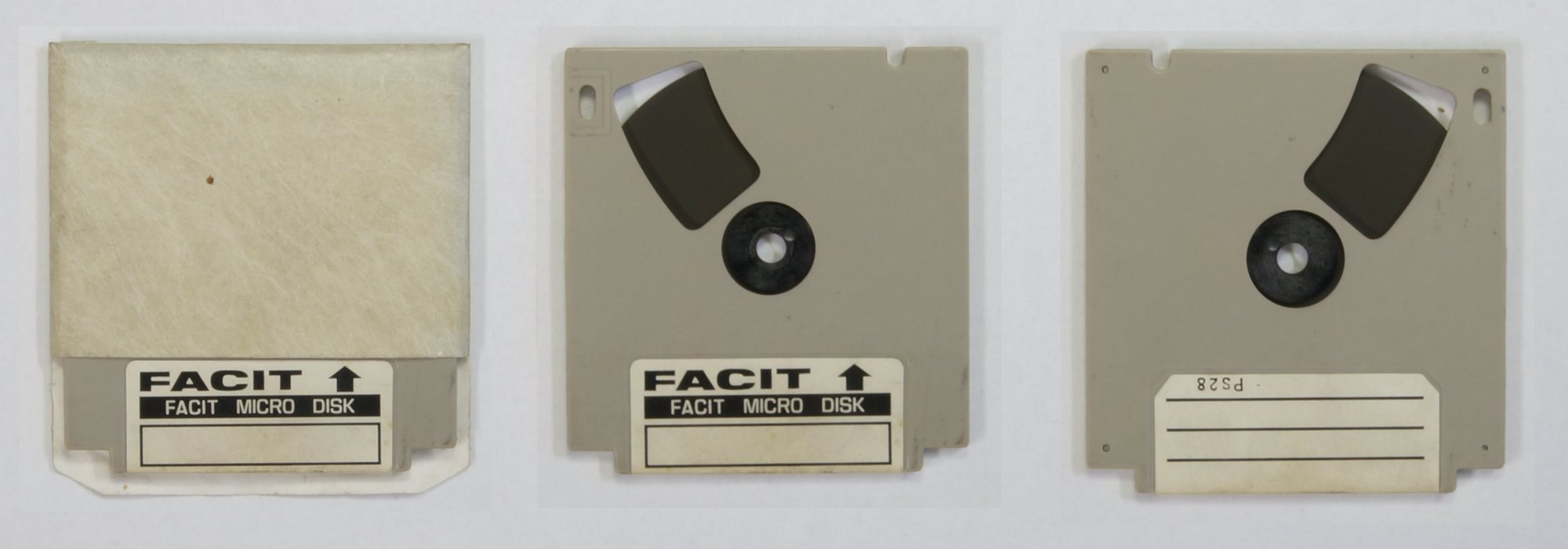
A latest option, the microfloppy disk drive.
Some parts :
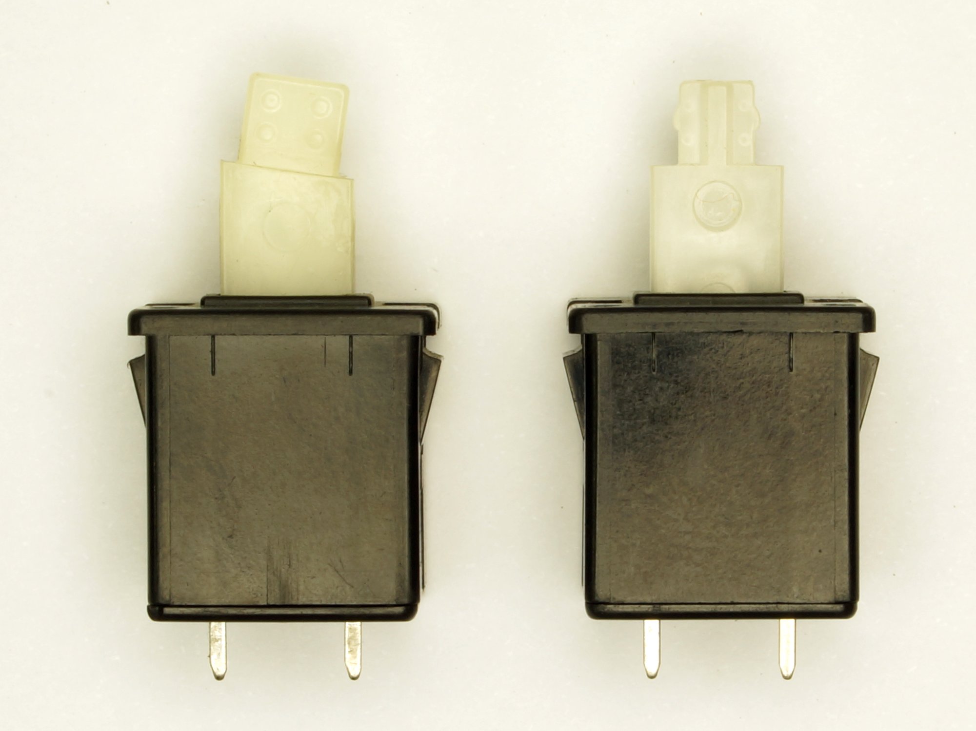
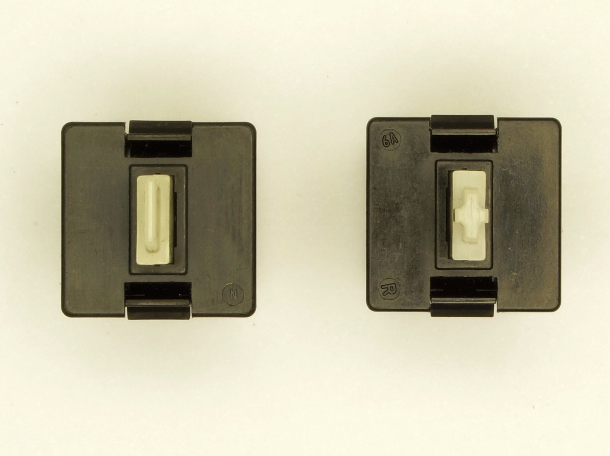
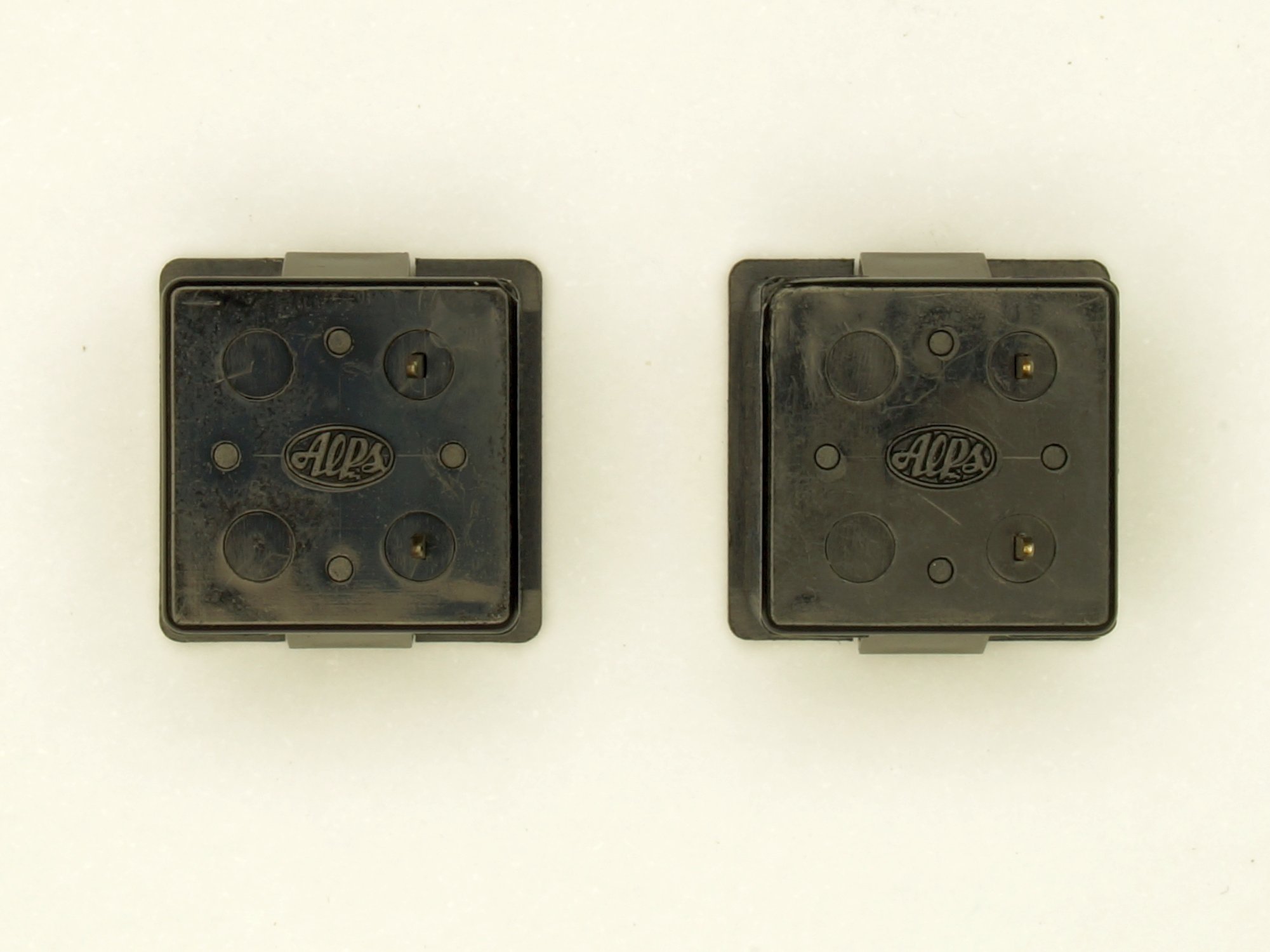
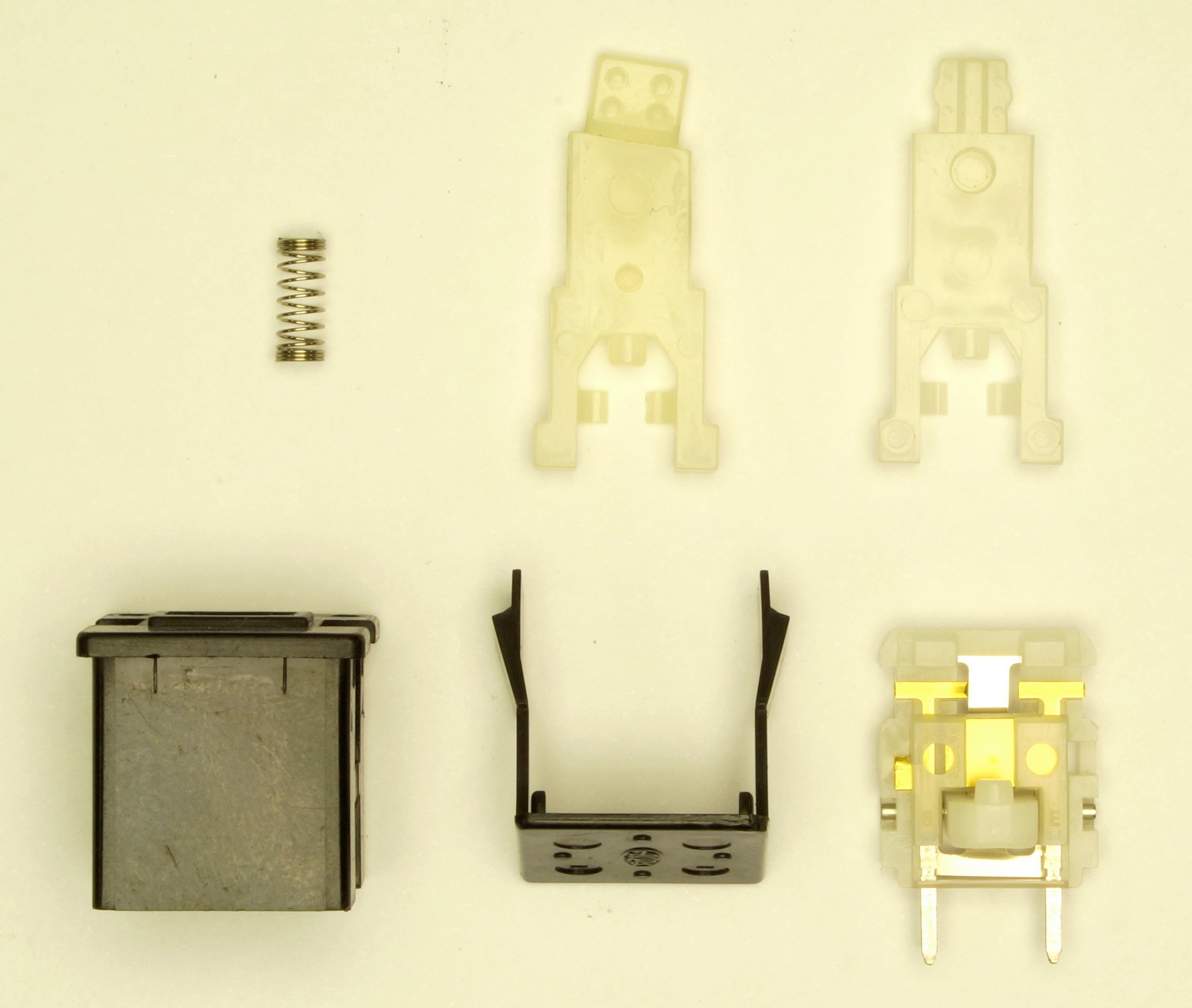
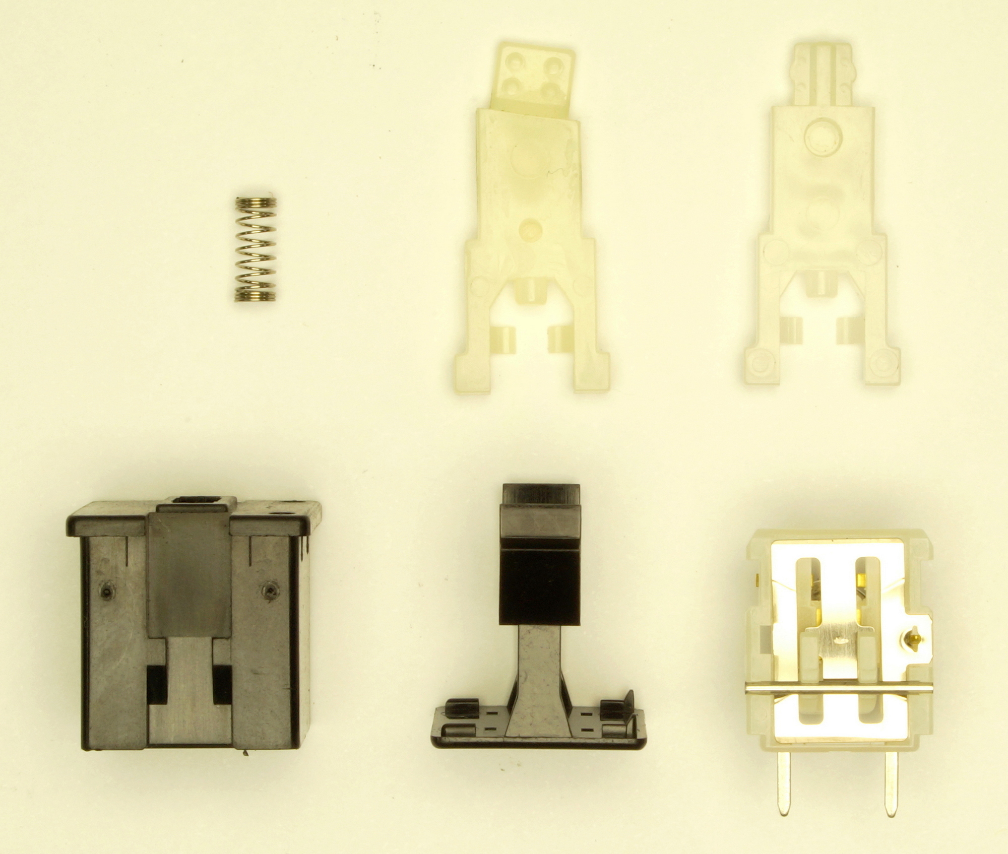
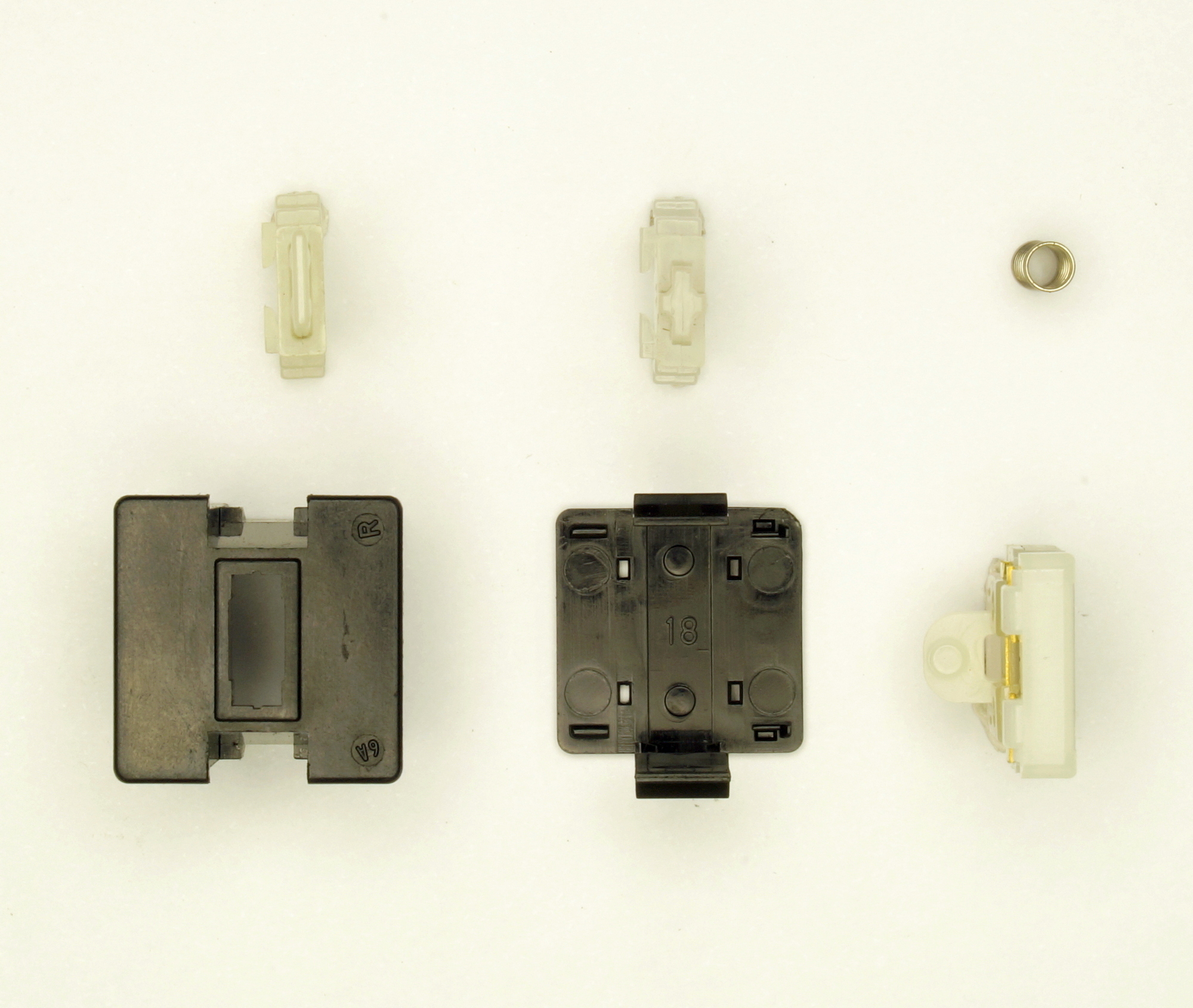
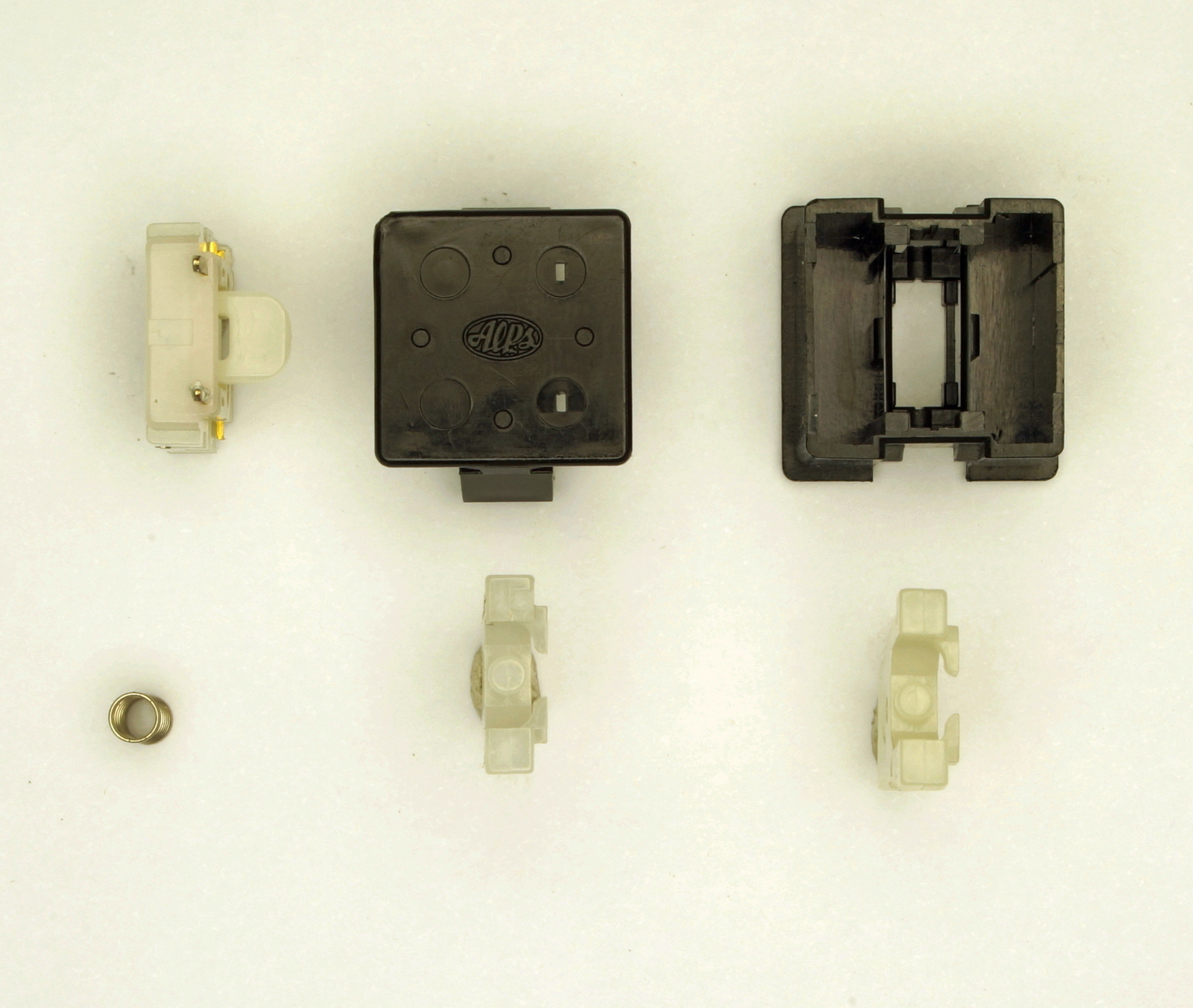
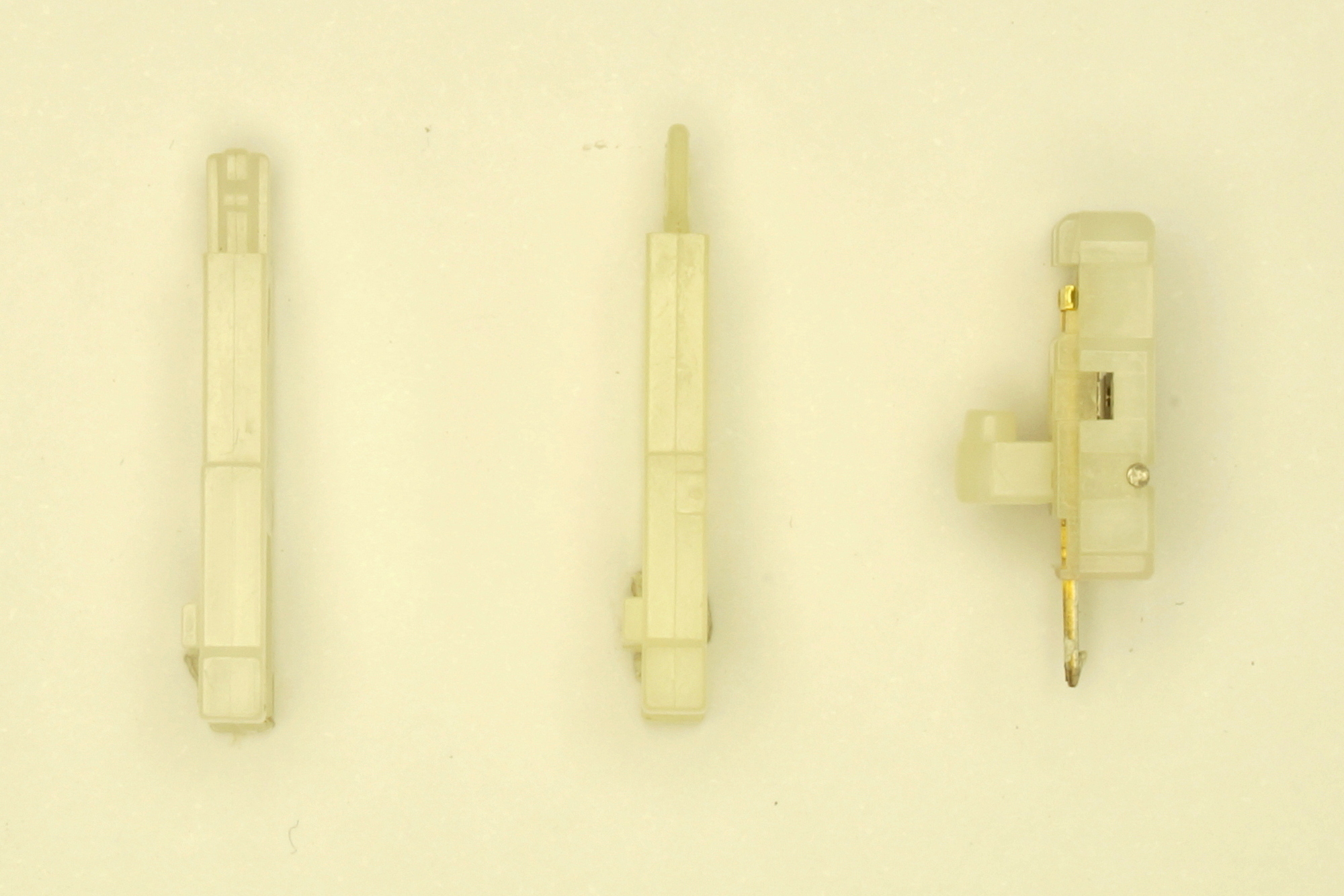
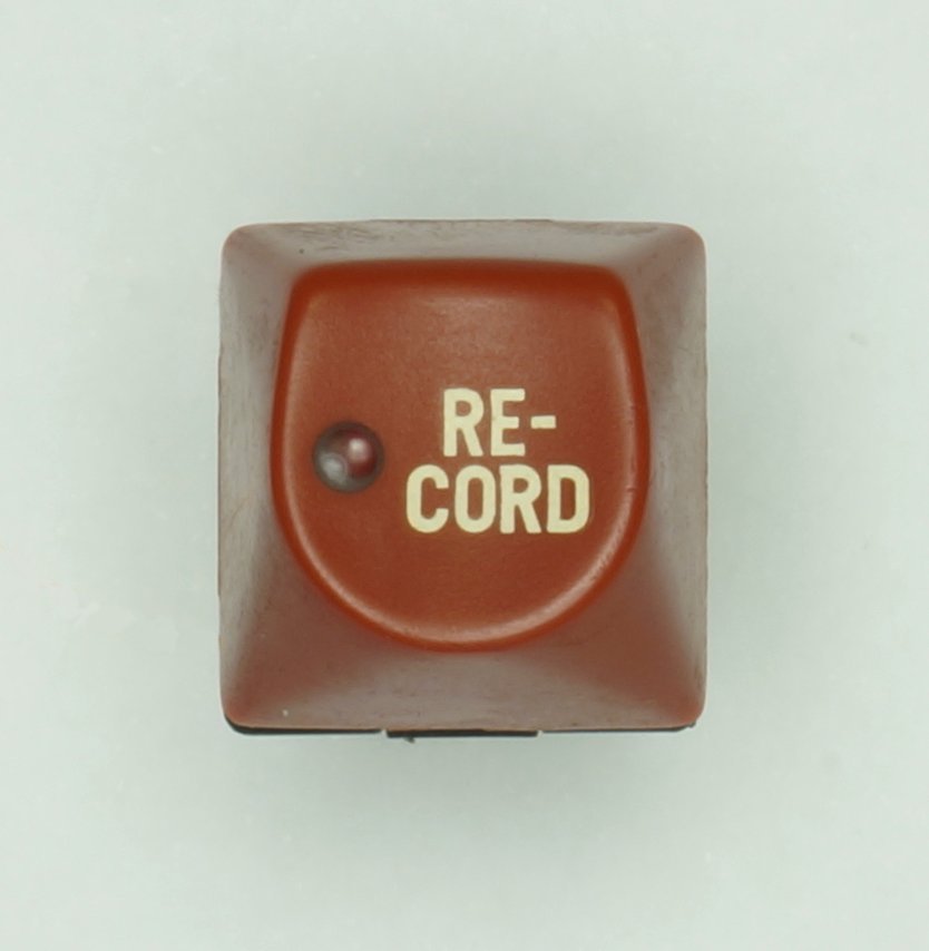
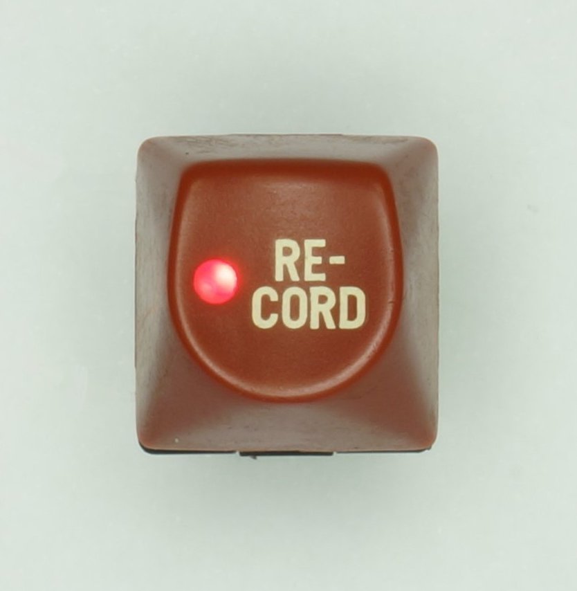
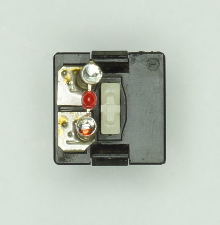
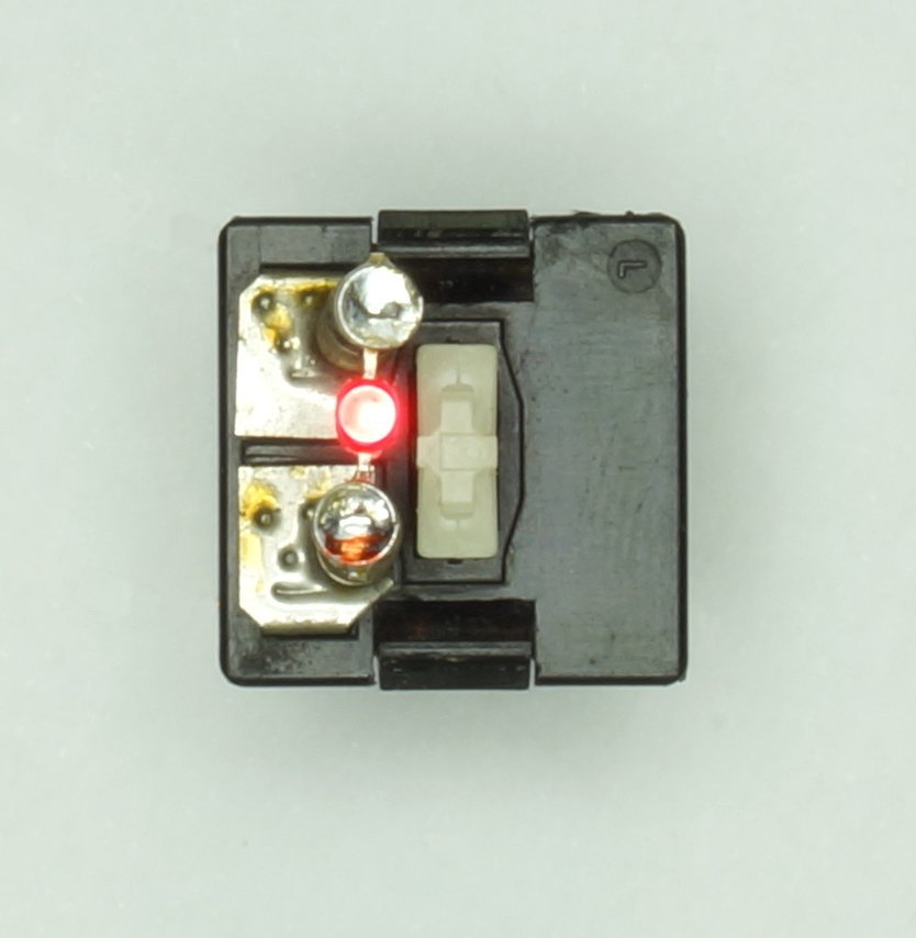
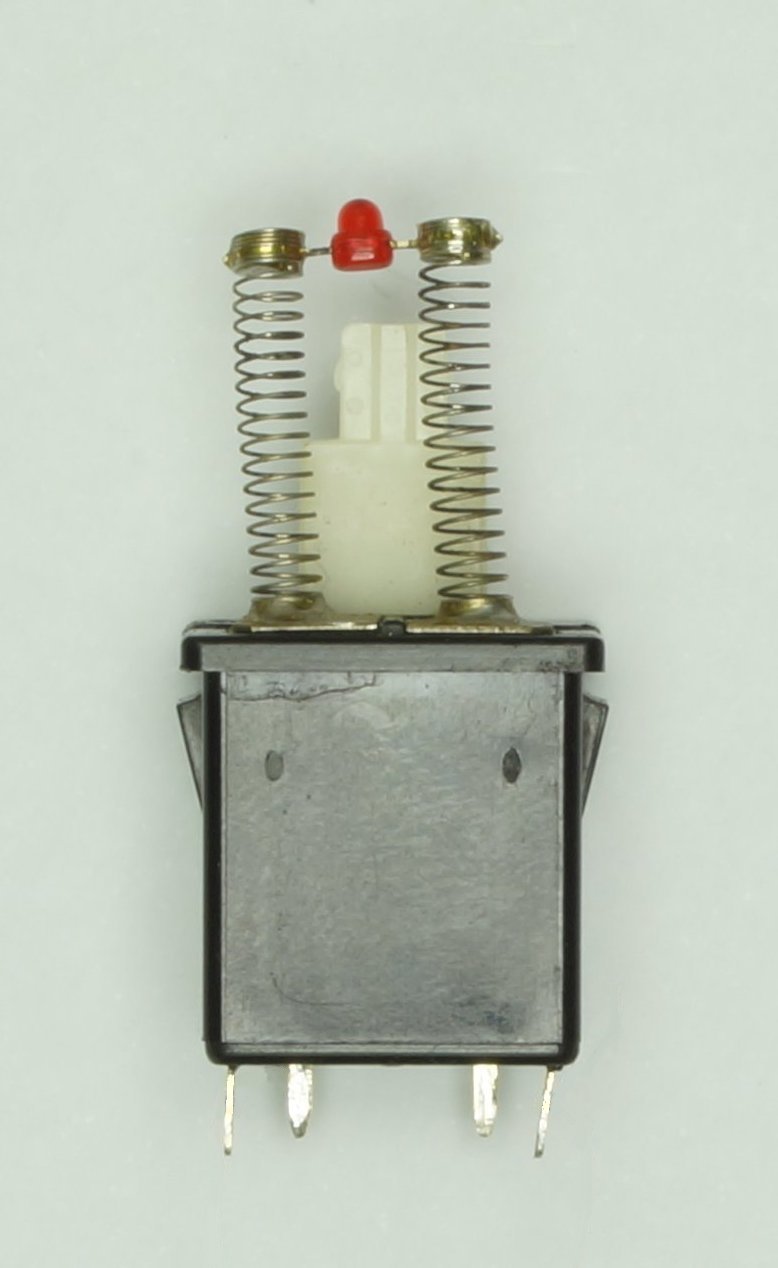
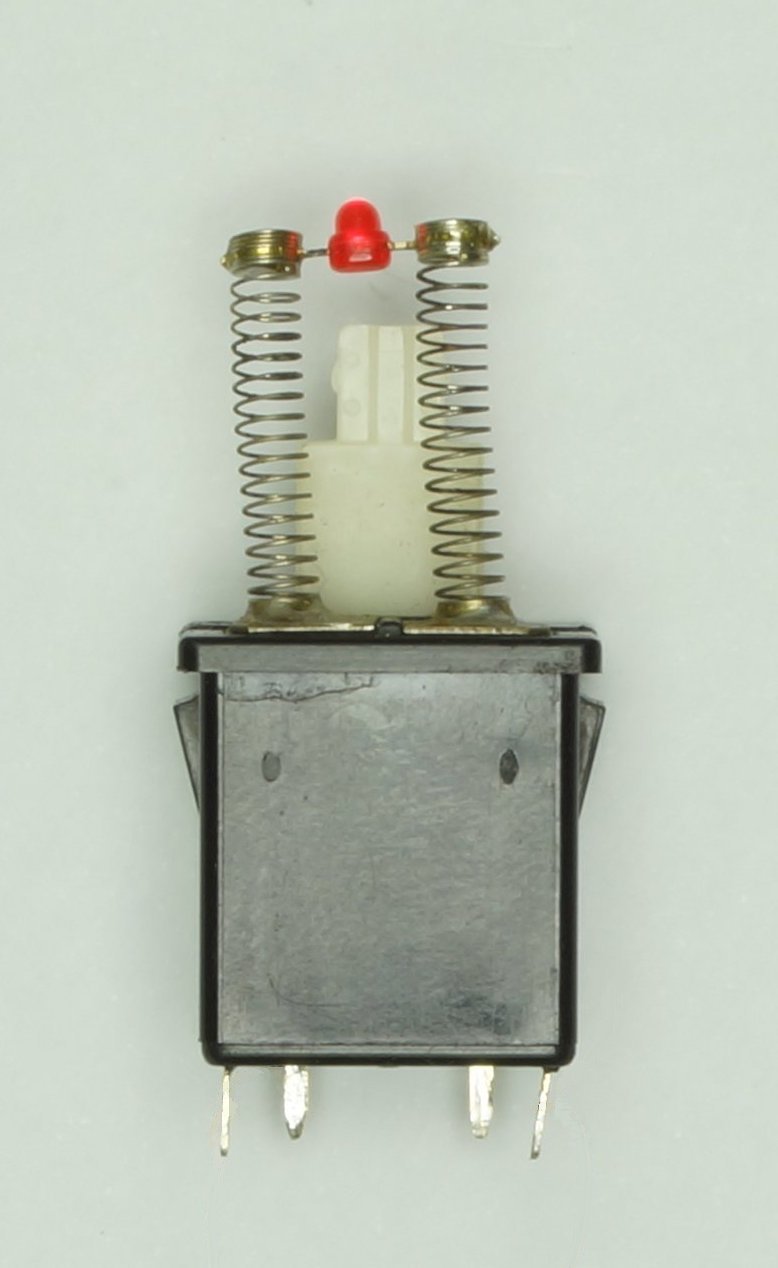
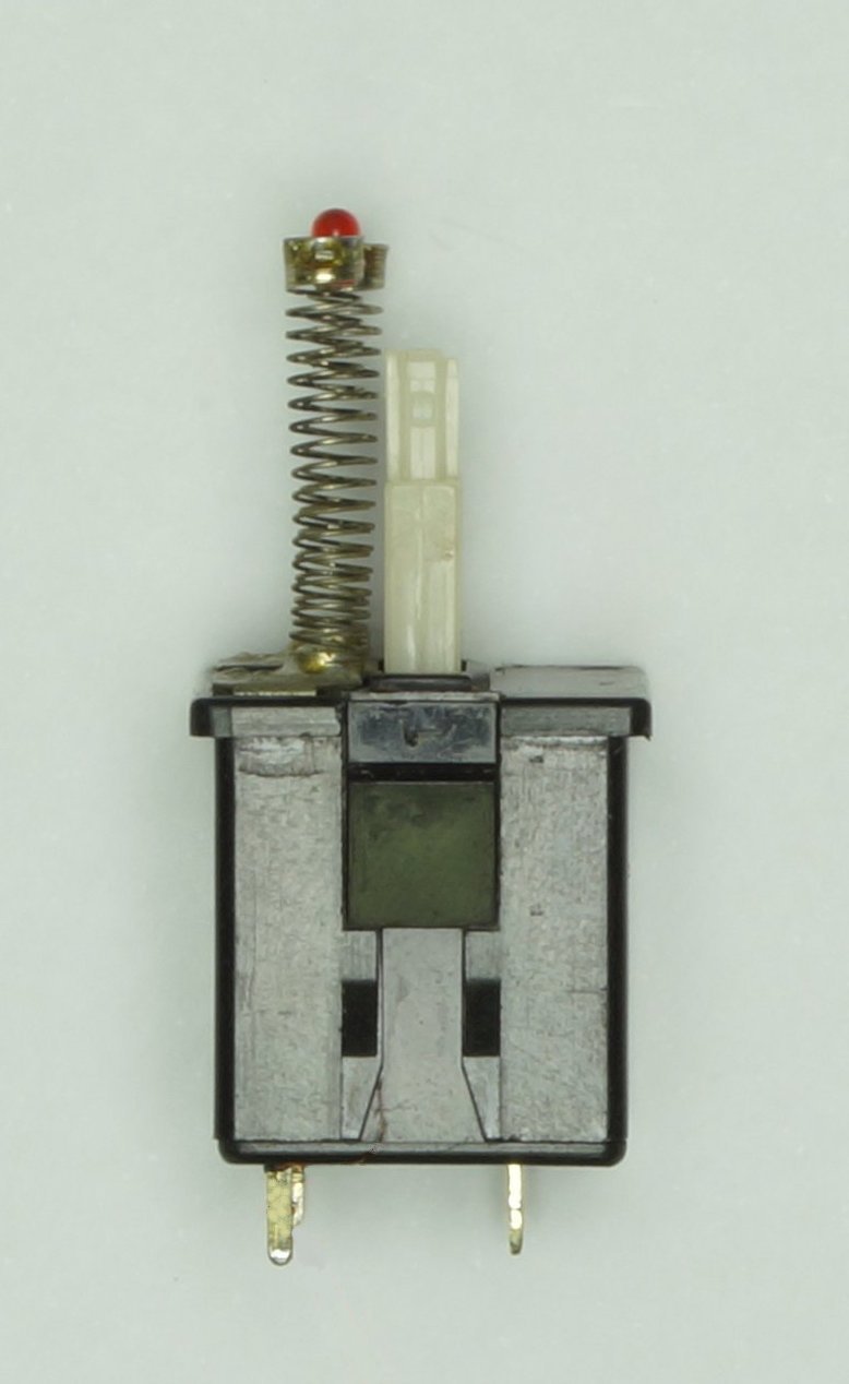
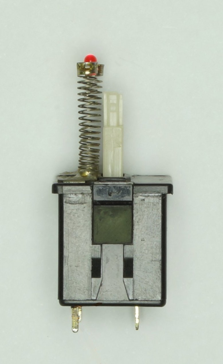
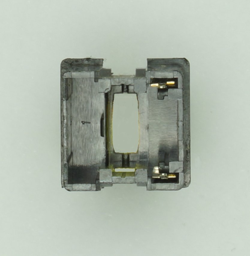
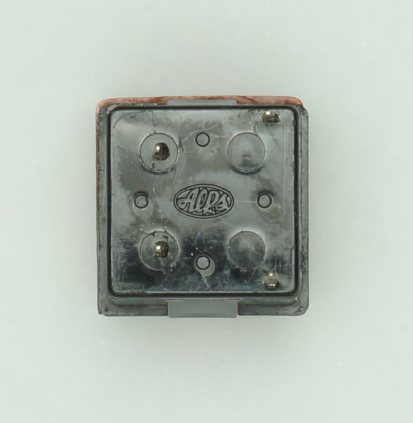
First, off course, the Keythority Alps SKFF.
The Motors :
This TPWR series uses 3 DC motors for the main functions where almost all the other on the market were using stepper motors.
Advantages were a much higher motor torque making possible a high speed in carriage and printwheel moving without the noise of the stepper motors.
But this needed a more complicated and expensive driving section. On the control board, only two IC are needed to drive the unique stepper motor used to feed the ribbon and almost all the rest is used to control the speed and position of the 3 DC motors.
The Carriage or platen motor.
They are DC motors and are practically the same, the only difference is the chopper wheel with a different number of steps.
There are three connections,
1 - the power is connected to the left, the red and black wires.
2 – a small DC generator, called tachometer, sends a speed feedback to the control board, the yellow and orange wires.
3 – under the black cover, a chopper wheel at the end of the shaft interrupting the light barrier of an optical sensor produces pulses corresponding to one micro-step used to calculate the carriage position or the paper feed. The platen (paper feed) has no home position. For the carriage, when the power is switched on, the carriage is slowly moved to the left, when stopped by the carriage stop (rubber or ABS, see the frame higher), the direction is reversed and after a small number of micro-steps ; the home position is automatically set.
The chopper wheel,
with two models of optical detectors used,
The printwheel motor.
This is also a DC motor, having the same three parts, for the position here two sensors : one producing one micro-step for each character of the print wheel and a second for the home position.
The home position sensor is the bottom one, the contacts + and – are the « brushes » from the tacho producing the speed feedback.
The cover with the tacho output removed to see the chopper wheel, the home position is the longer line on the left of the bottom detector, the tacho and the two optical detectors.
Detail of the home position on the chopper wheel.
The tachometer roughly cleaned.
After cleaning.
The metallic « brushes ».
Now cleaned.
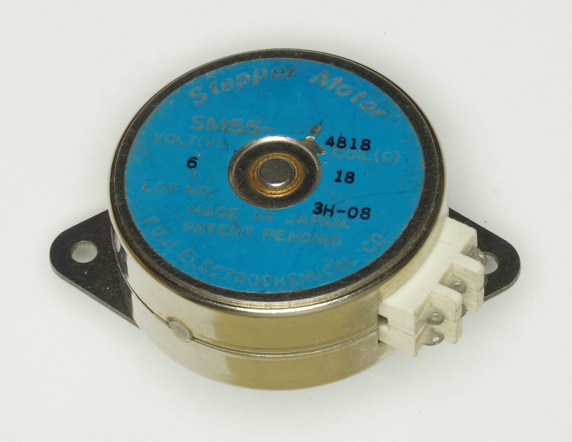
The ribbon feed motor.
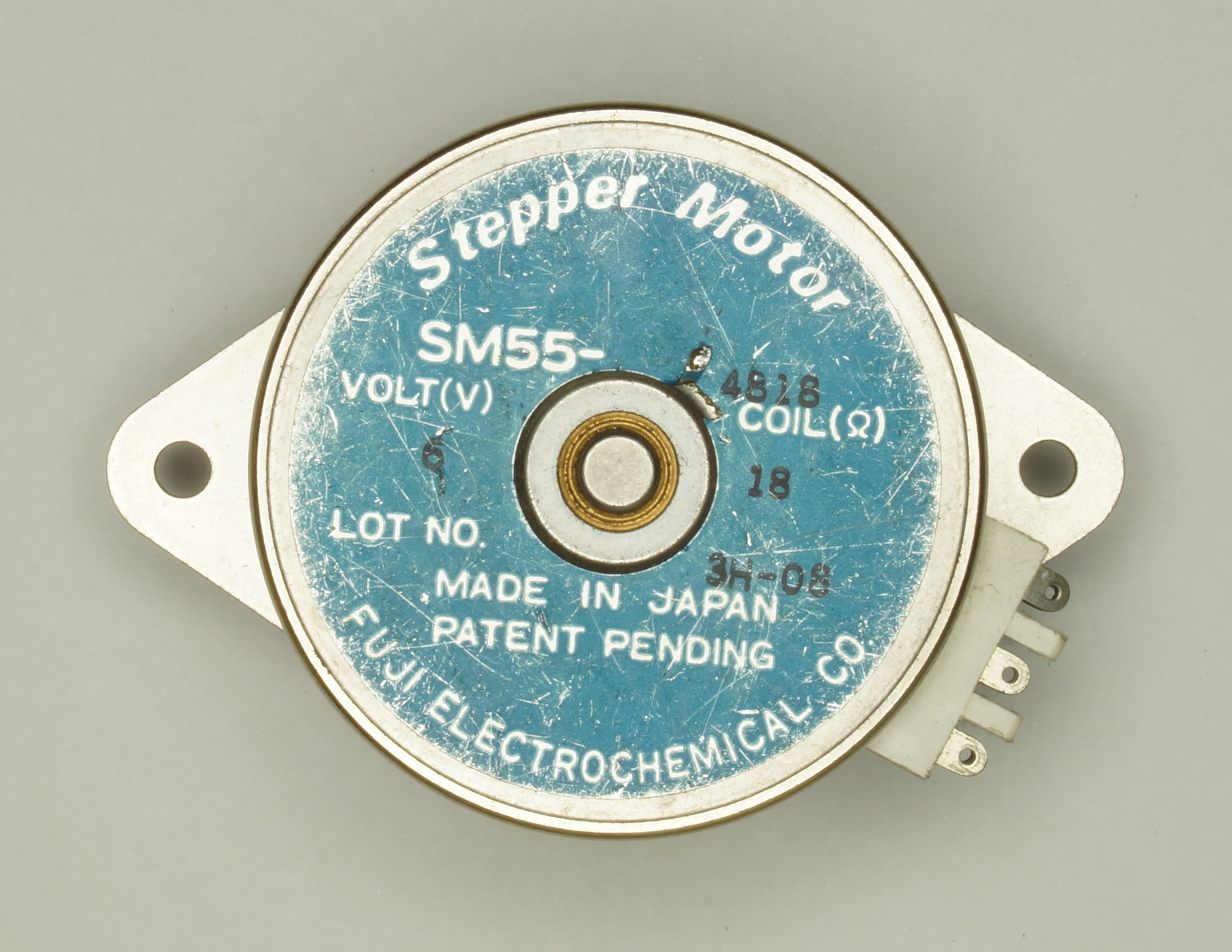
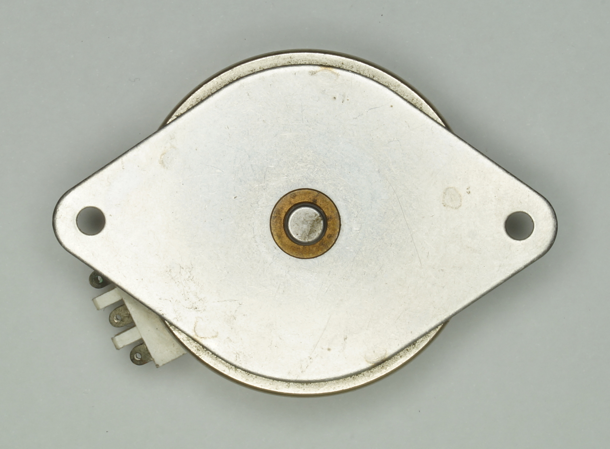
The only stepper motor in the TPWR, 6V, 15°/step, 24 steps/turn.
Another typewriter in the same series as the 8111 presented by Haata photos-videos-f64/facit-8111-2-typewriter-t12424.html and the typewriter/Invoicing machine 6480 presented by purdobol photos-f62/facit-6480-typewriter-calculator-t17719.html
That’s how it looks now, but not one month ago, I just put it in 2002 in a plastic bag, not cleaned after using it for 5 years as printer. More, the foam used as sound absorber inside de covers and on the mechanical frame was falling as dust when touched.
A few pics at the beginning from the bottom cover to remember me the wiring modifications I made 30 years ago.
Now, it’s cleaned !
The CPU board Facit 8121, microprocessor 8088, 7 EPROM’s 2764 8Kx8 for the program and 24 Static RAM 2Kx8 Toshiba TC5516 or NEC µPD449.
The serial interface RS232 (or V24) combined with the micro-floppy interface was an option, FACIT add then KSR for Keyboard Send & Receive to the model name. (see EPROM D35)
Can be used to receive data to print and/or to send data to a mainframe or even to another TPWR. As terminal, can be configured in full duplex, the characters typed on the keyboard are only sent to the other device, or in half duplex, the characters are then sent to the other device AND reinjected by the UART in the receive buffer to print a local copy at the same time.
Standard was the TPWR sold with only the small micro-floppy interface as the one in the Haata’s Flickr Album https://www.flickr.com/photos/triplehaa ... 0265552743 middle of page two.
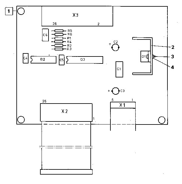
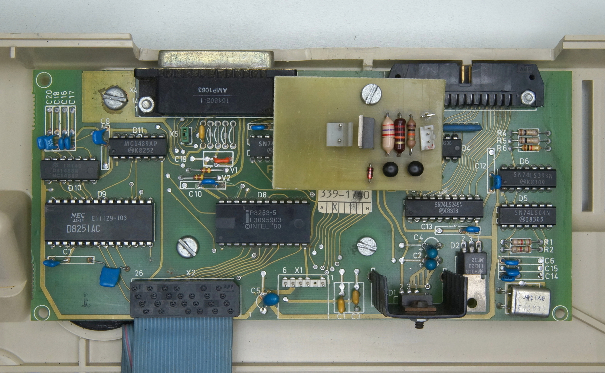
Now with the Cooling fan driver I quickly made to replace the one on prototype board. The cooling fan was installed on the printer-only of the same series, the 4560.
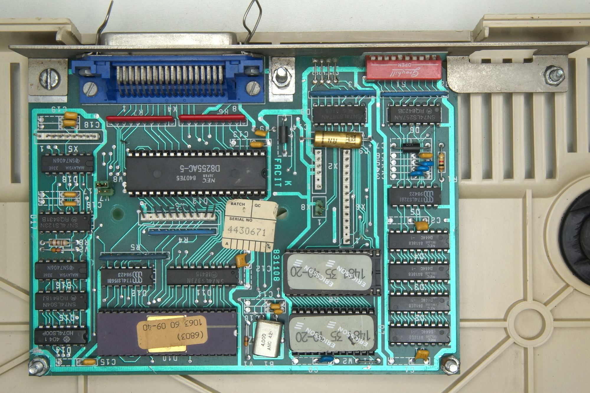
The parallel interface (or Centronics) was not an option but was used on a basic model 7900 or 8001 as receive only cheaper printer option.
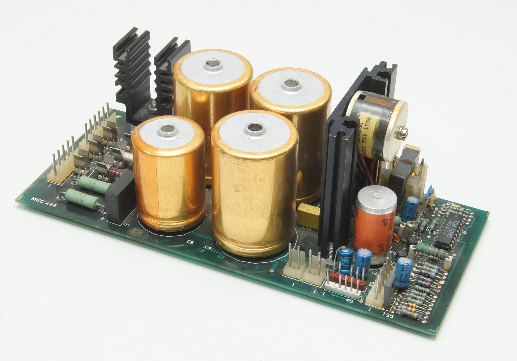
The power supply, a little more power than the 8111 or 6480 to also drive the dual bin cut sheet feeder option.
The control board, the driver for the 4 motors, the hammer and more.
The bottom plate almost complete.
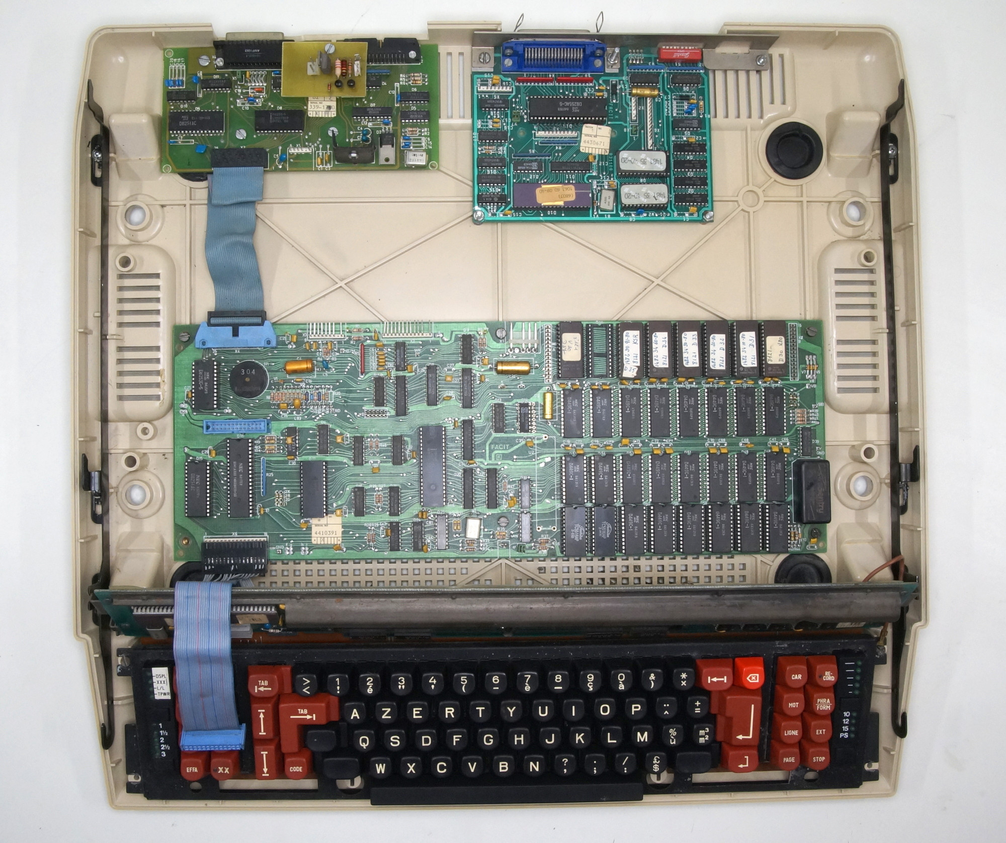
The cleaning of the ribbon feed.
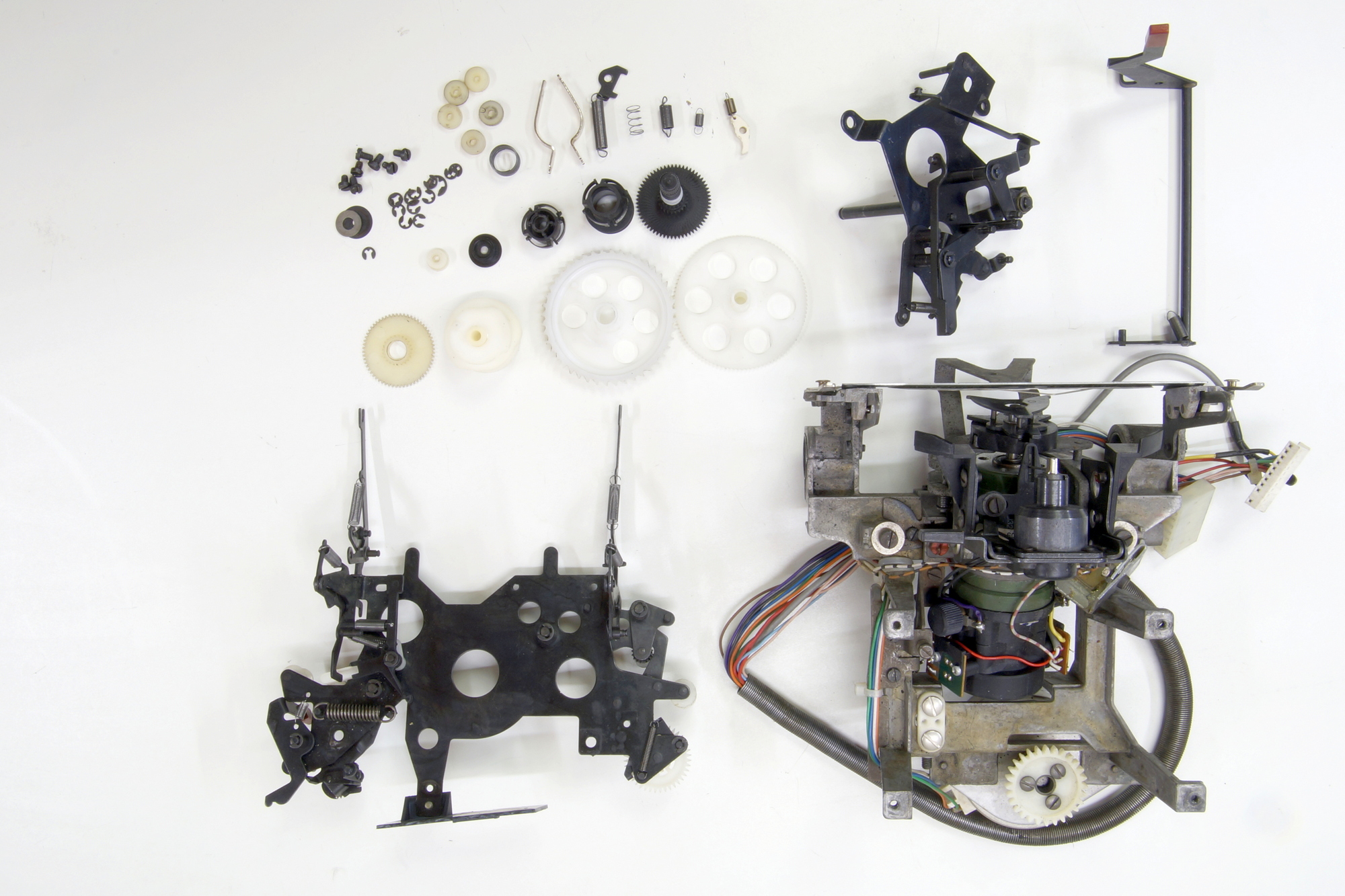
The driving parts.
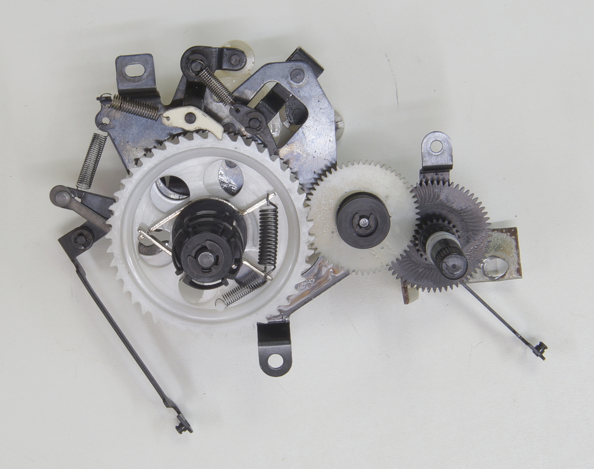
Now, just to reassemble
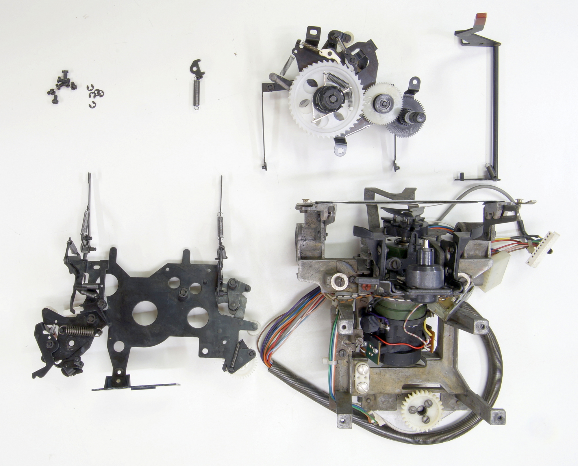
The ribbon feed, top view.
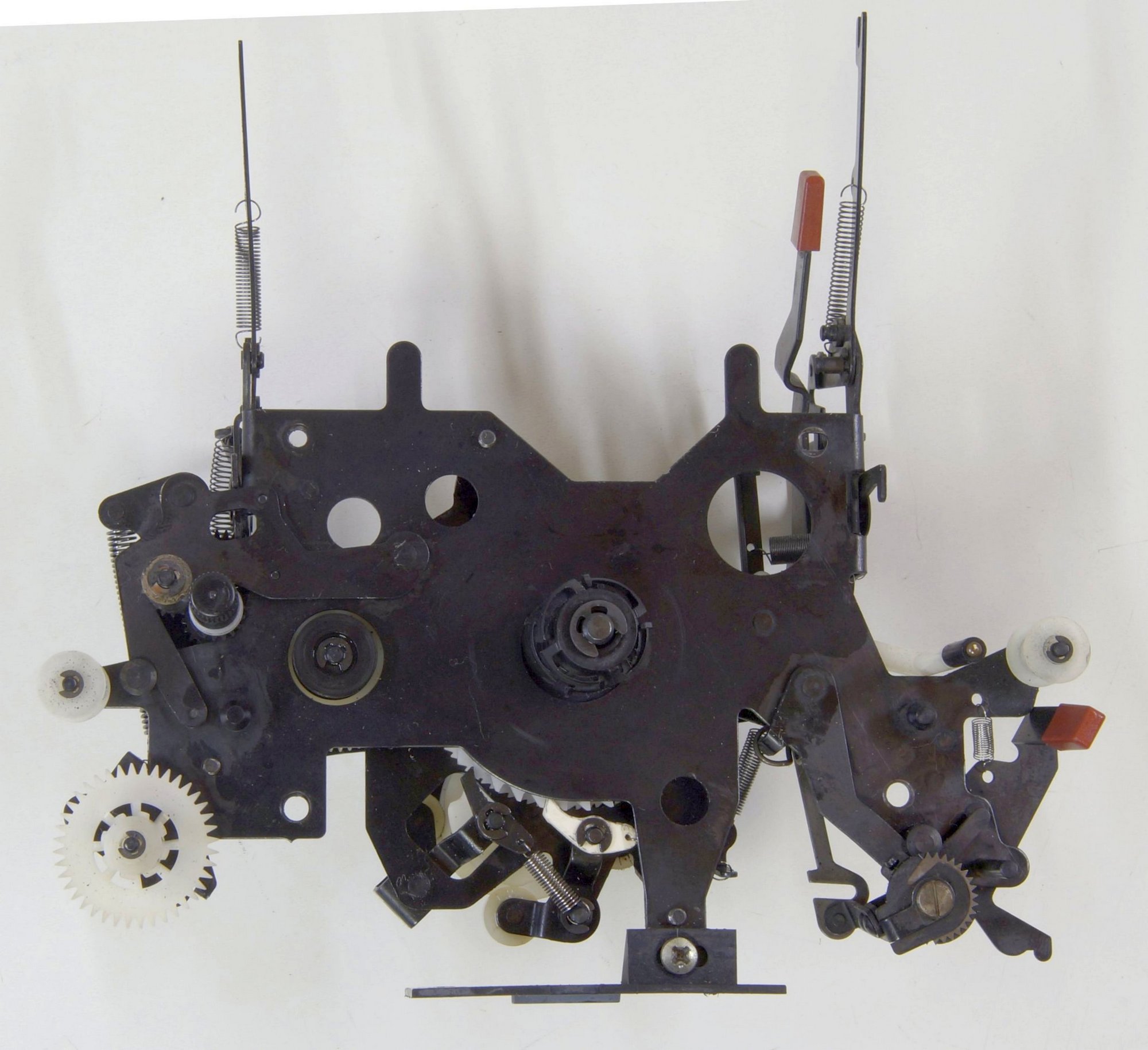
Bottom view
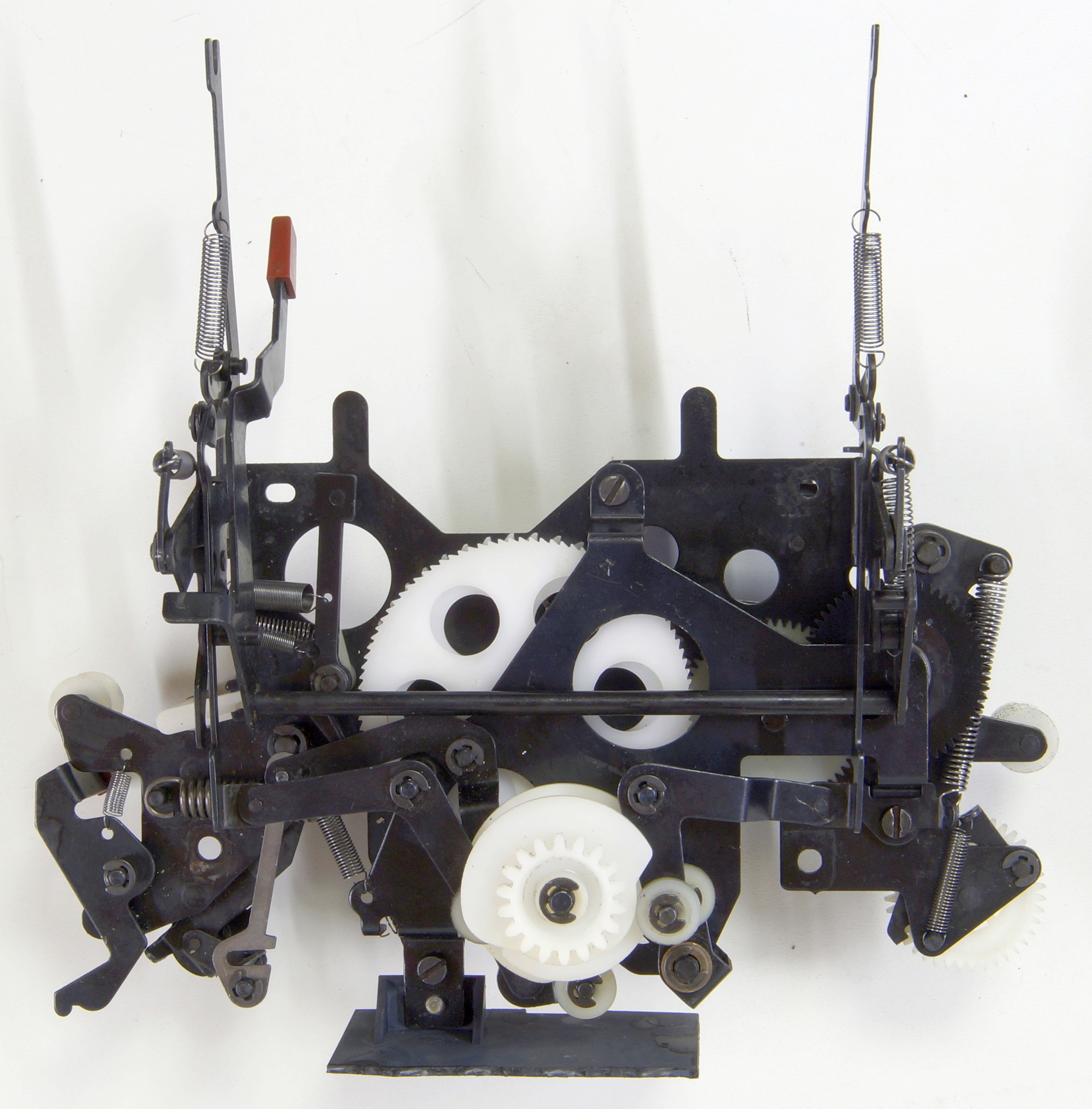
The carriage complete.
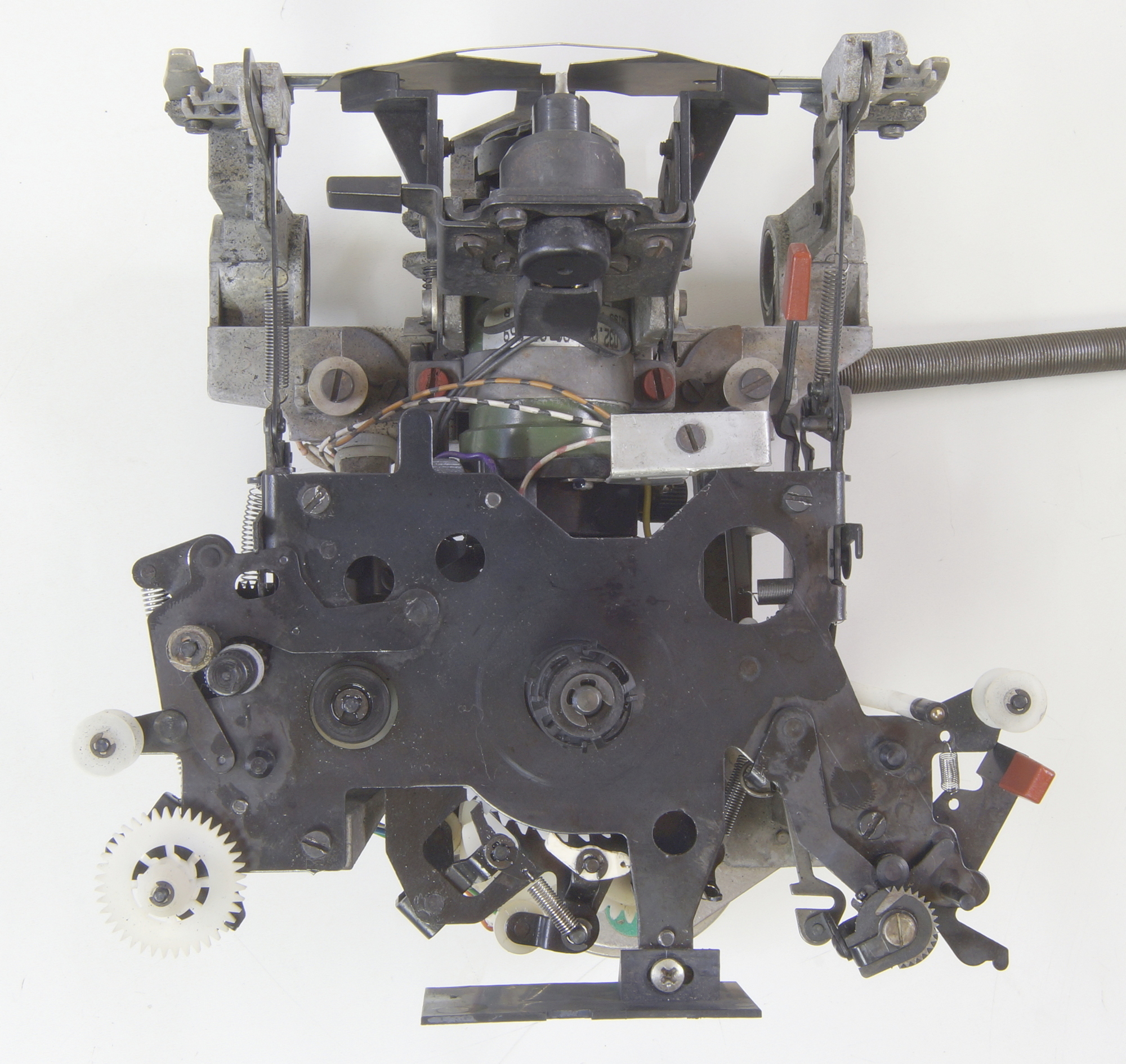
The frame
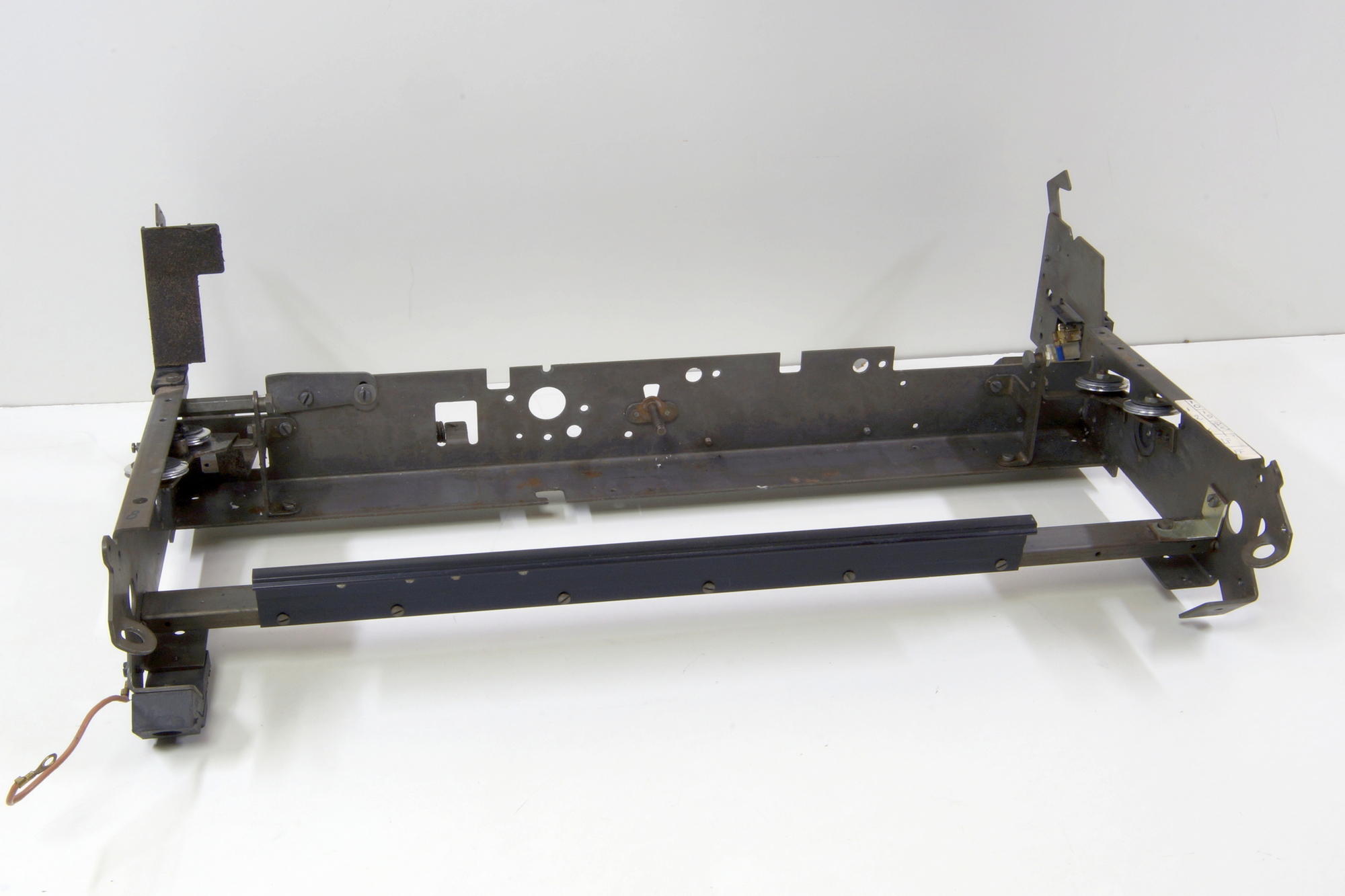
At the right-hand side, you can see why this machine was taken out the stock, I could use it as spare parts but preferred a quick (ugly too, I agree) repair and use it as test machine to repair the electronic boards replaced in the field or by our local resellers.
It should look like this.
The carriage, the carriage motor with the drive pulley, the belt and the wires, and the transformer back in place.
A little bit too fast, these rubber carriage stops are inflating when the rails are lubricated, a newer ABS model was made.
The new one.
With the power supply back in place.
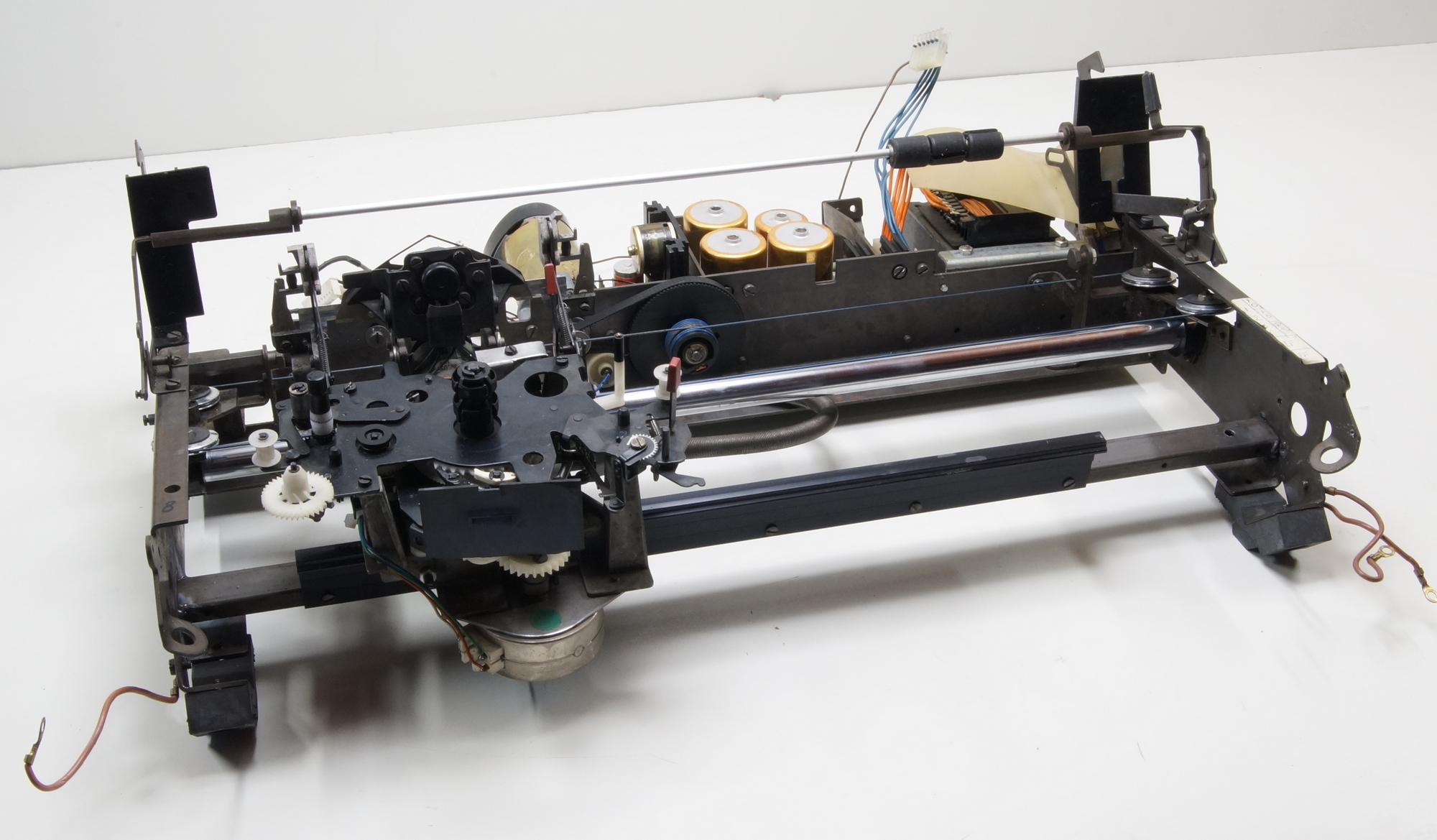
The frame back on the bottom plate, front view.
Back view without control board.
With the control board.
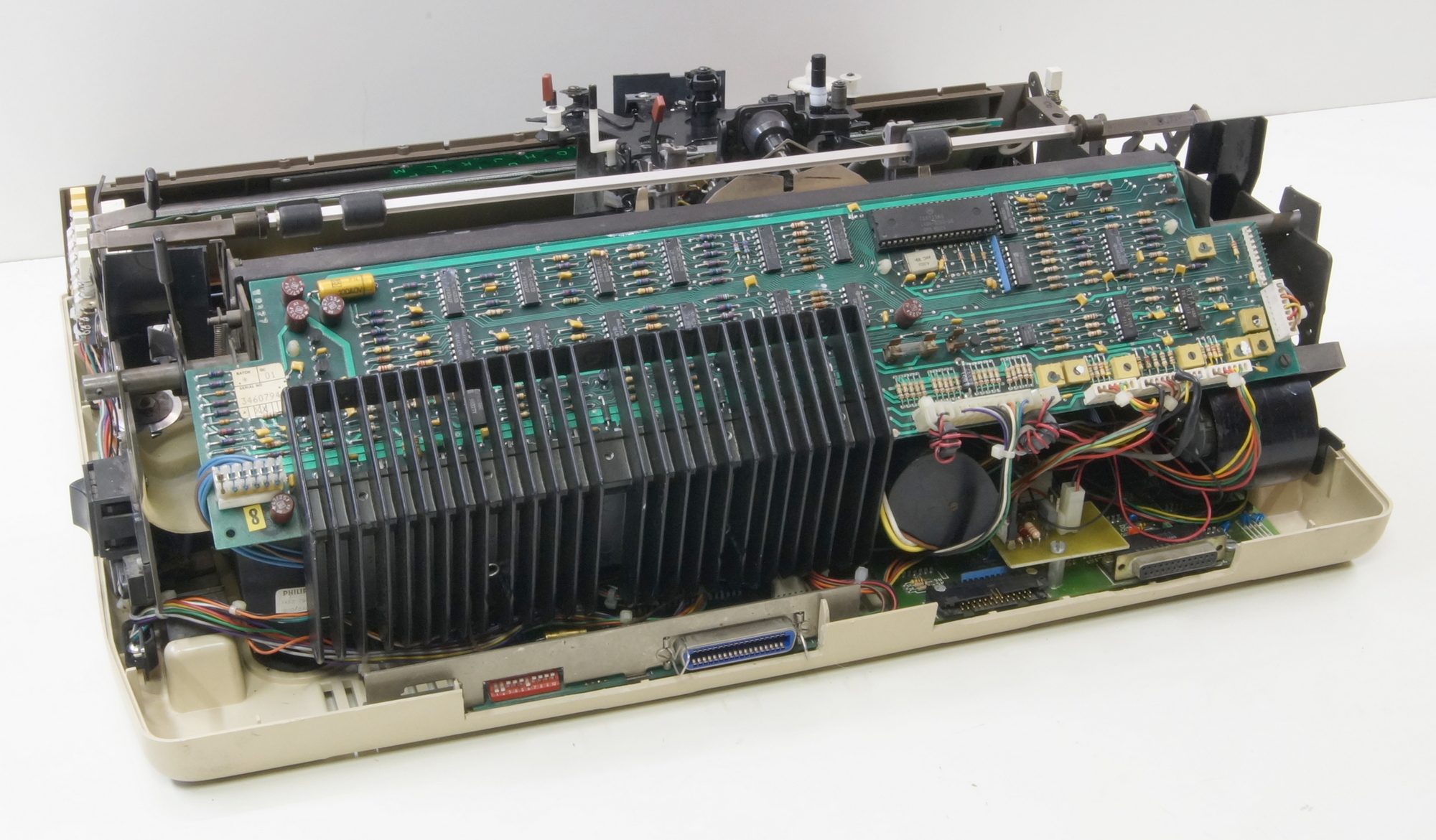
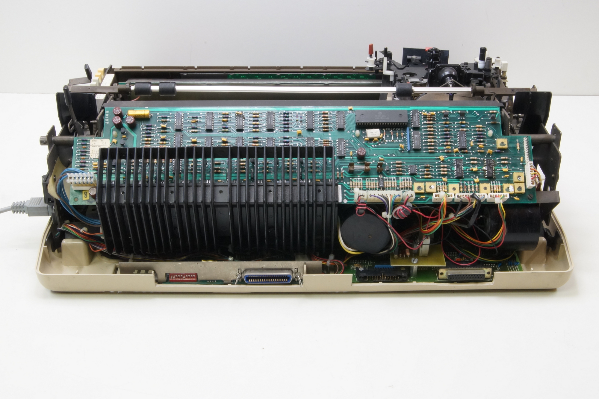
Ready to switch the power ON.
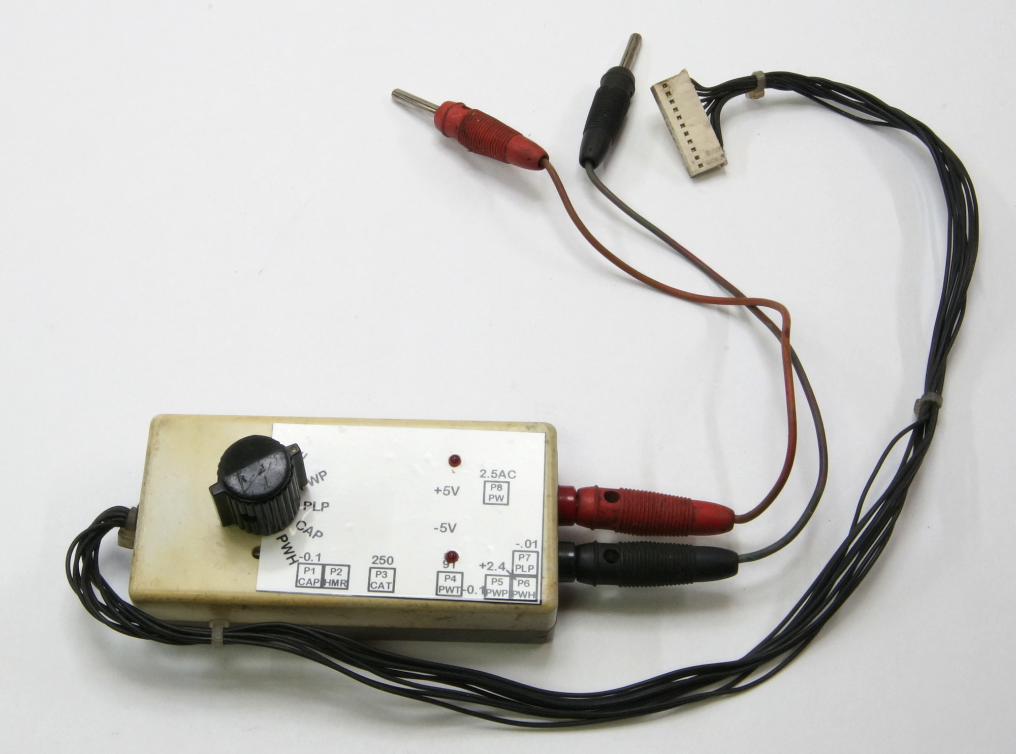
But first, the cleaning the test box and drawing a new label with the trimpots and their adjustment values. The box is used to start the test program and adjust the speed of the motors (tachometer/velocity), also the shape and voltage of the signals (position) coming out the optical sensors and to adjust the position of the ribbon stepper motor on the right step.
The test program is running, you can see the carriage moving and the print wheel turning.
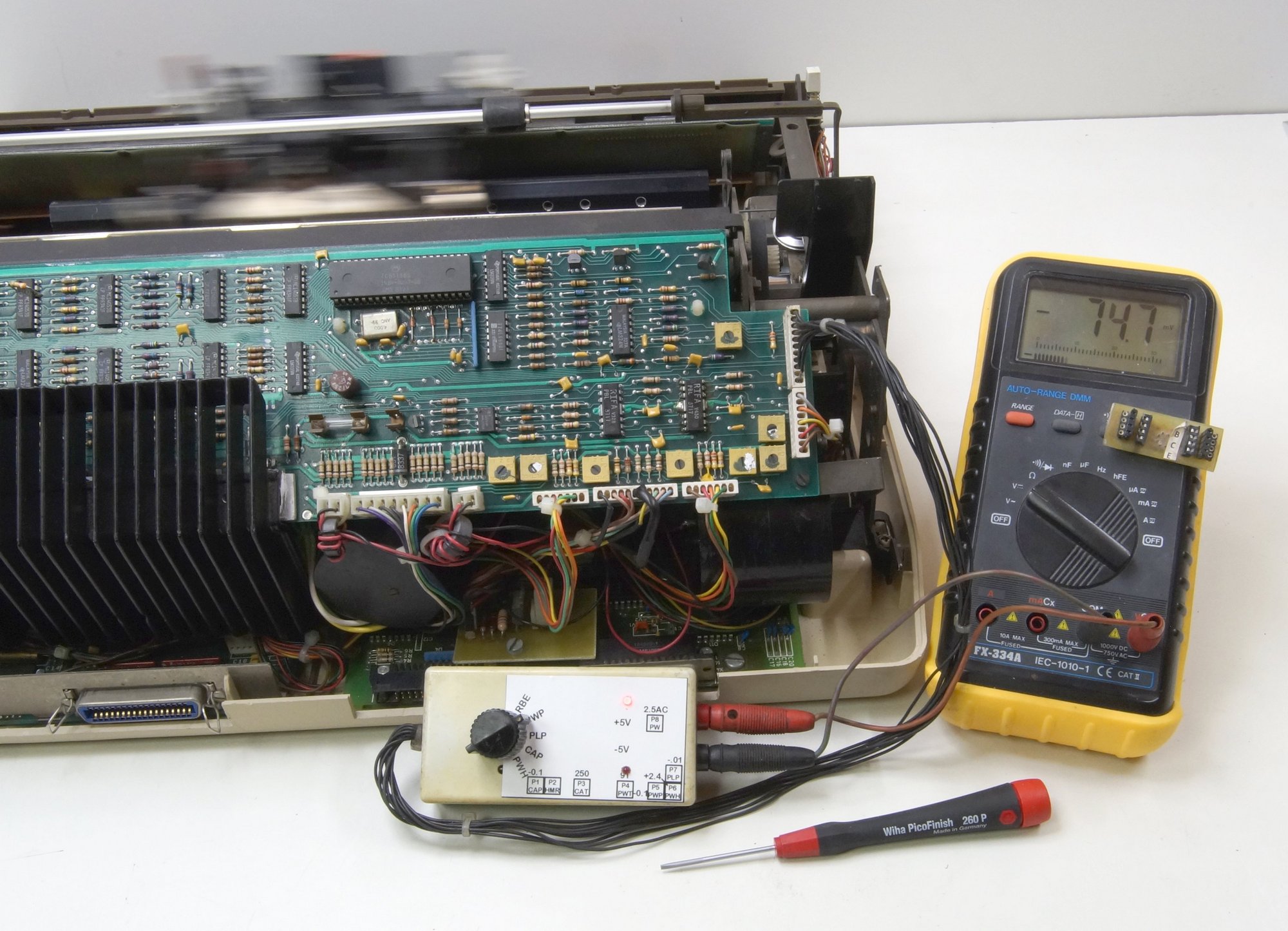
The preceding was with the original MicroController Motorola MC6801, here is with my own build MyController …
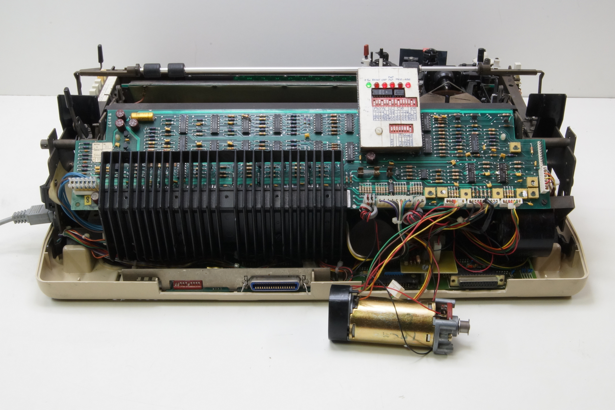
I made this to repair the control boards. Every output port of the microcontroller has his own dip-switch, the inputs one LED. I could check each step of the analogic speed (15) and direction for the printwheel and platen motors and the carriage motor (31). Also drive the stepper motor for the ribbon step by step (4) and adjust the current (4). Also included an adjustable pulse generator for the hammer.
The optical sensors of the 3 DC motors and the ribbon end are monitored by LED’s.
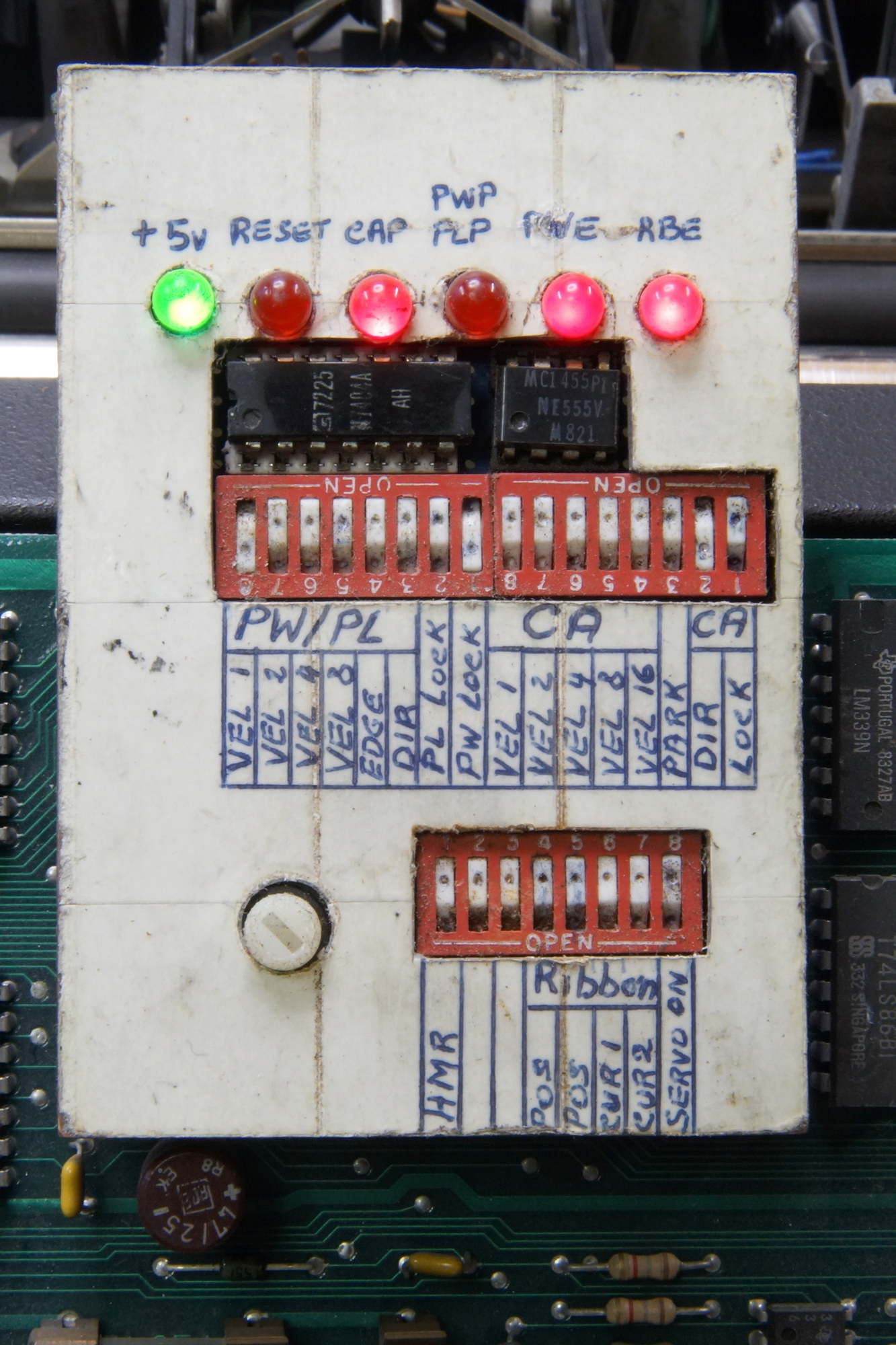
Here is the printwheel turning at velocity 13 and the platen motor is locked, the carriage motor should be moving at velocity 3 but I disconnected it for a steady photo.
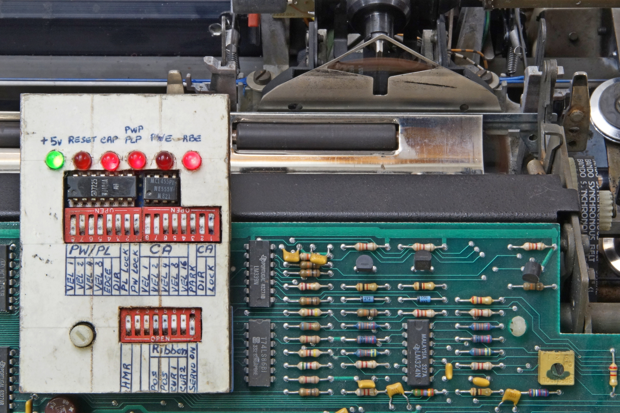
Here is the printwheel motor locked and the platen motor turning at velocity 1.
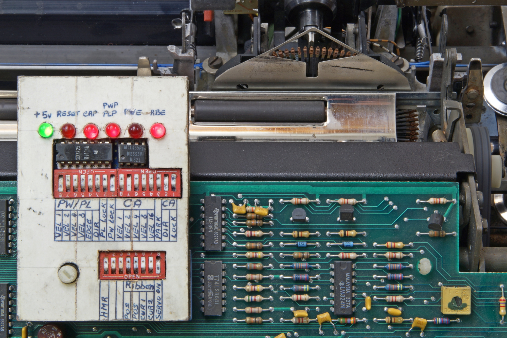
This is The Belgian keyboard layout.
The display should be replaced, I found only one, on eBay in the US, a little bit expensive, 65$ + 31$ shipping + customs.
After boosting the filament voltage a few volts.
Now the printing tests.
Rebuilt with covers.
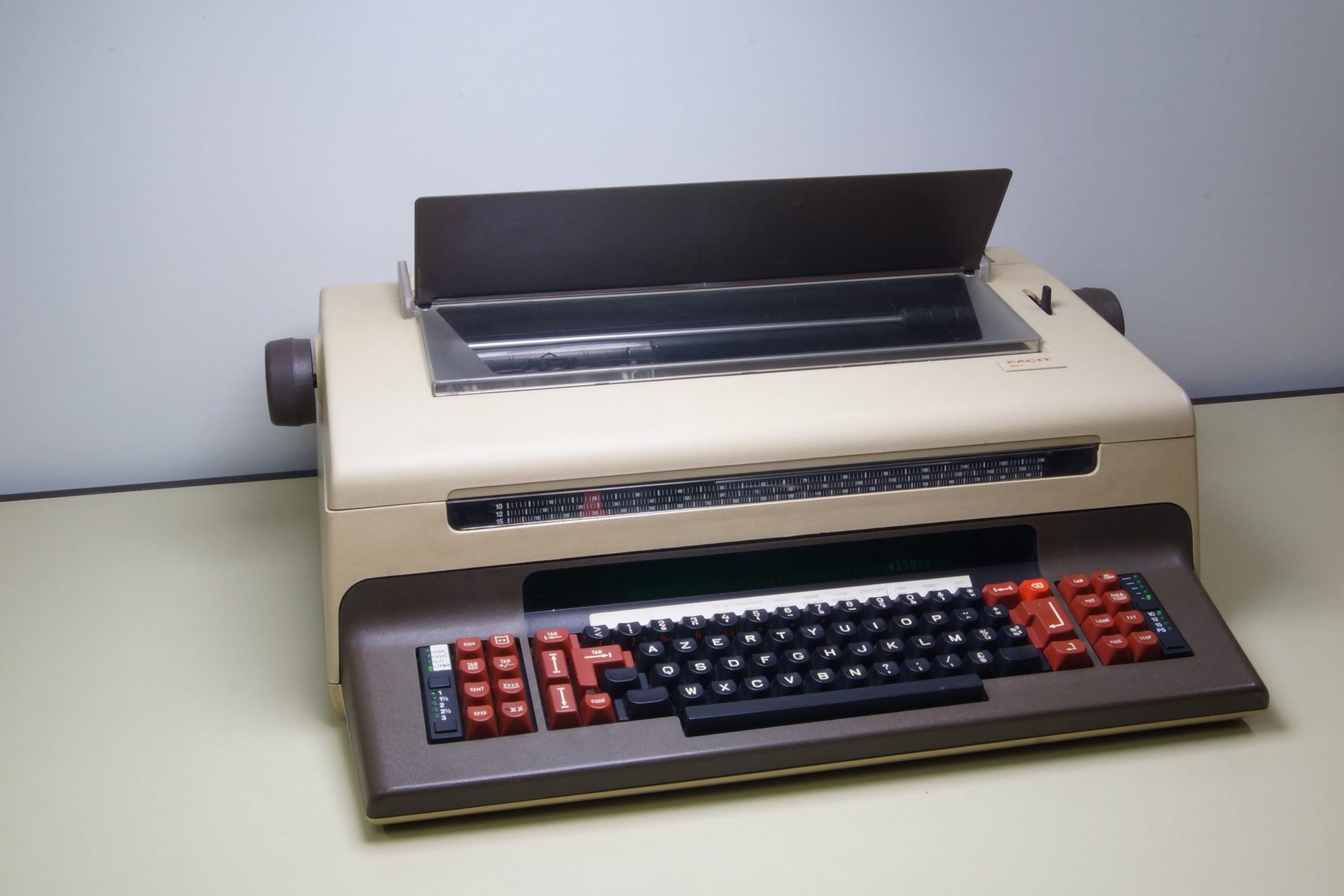
These knobs are missing on Haata’s TPWR !
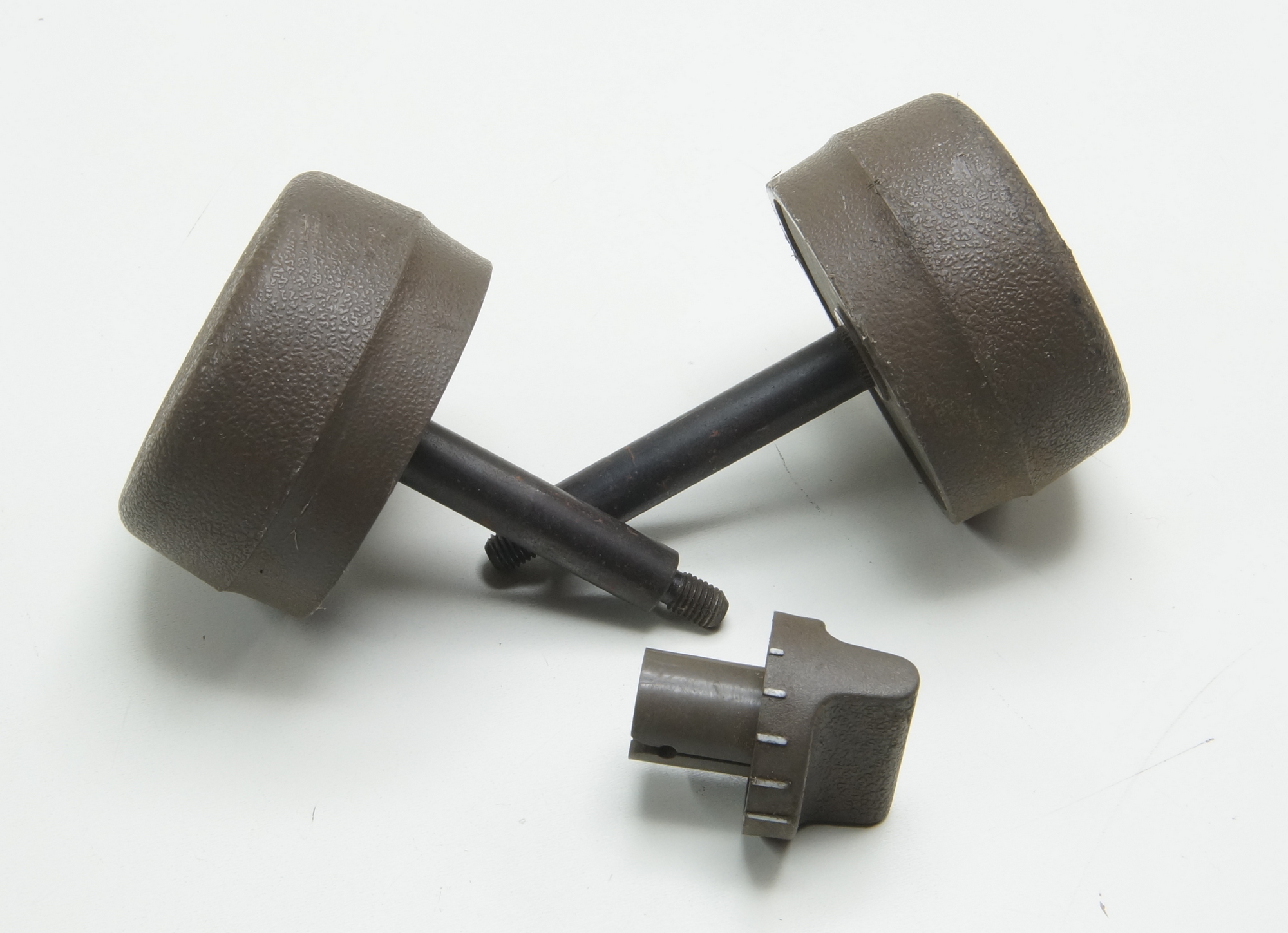
Another option the Tractor Feed also called Pin Feed, with longer knobs shafts.
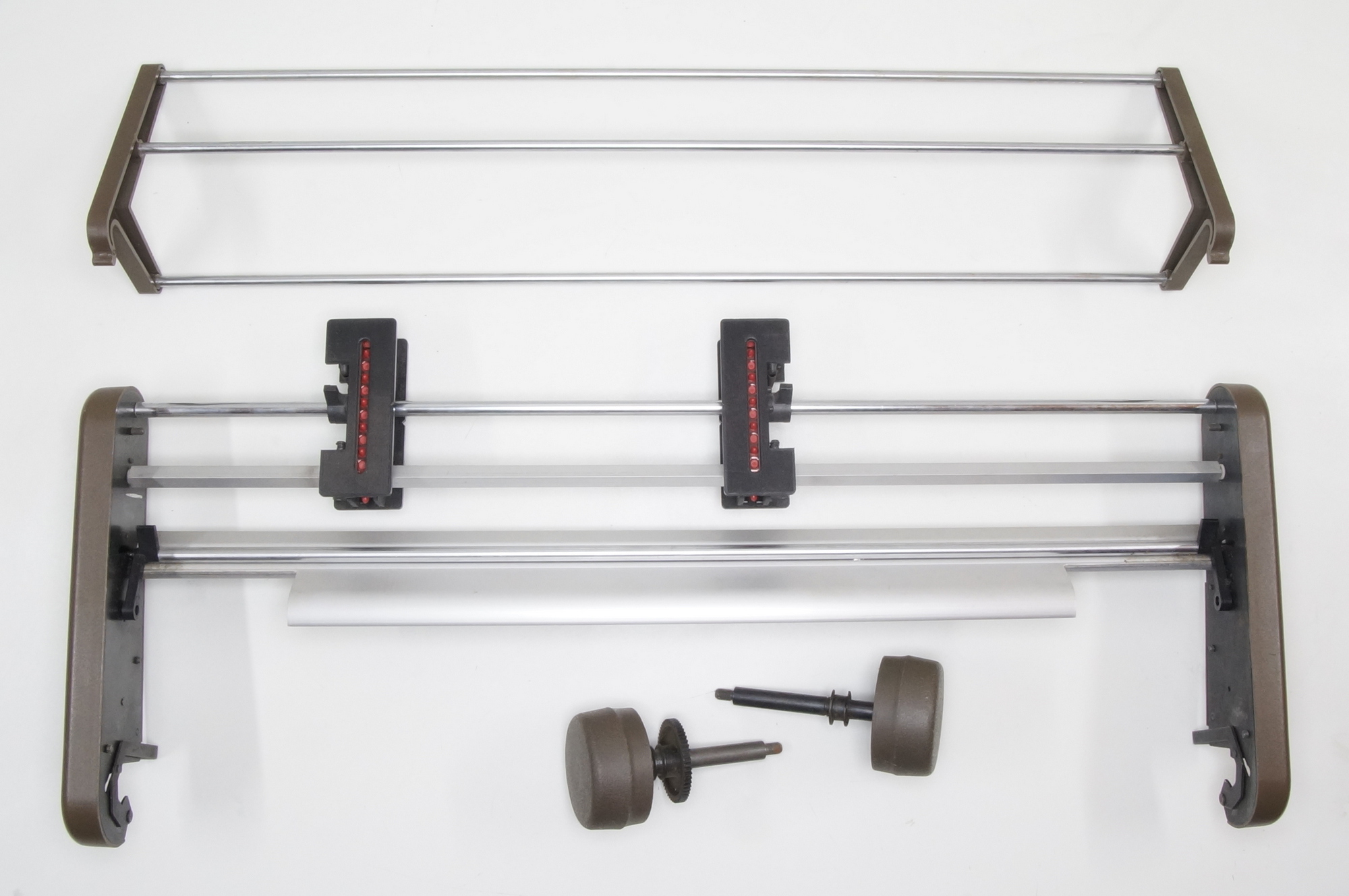
One cable is missing, the paper end sensor connected under the right cover.
With standard knobs.
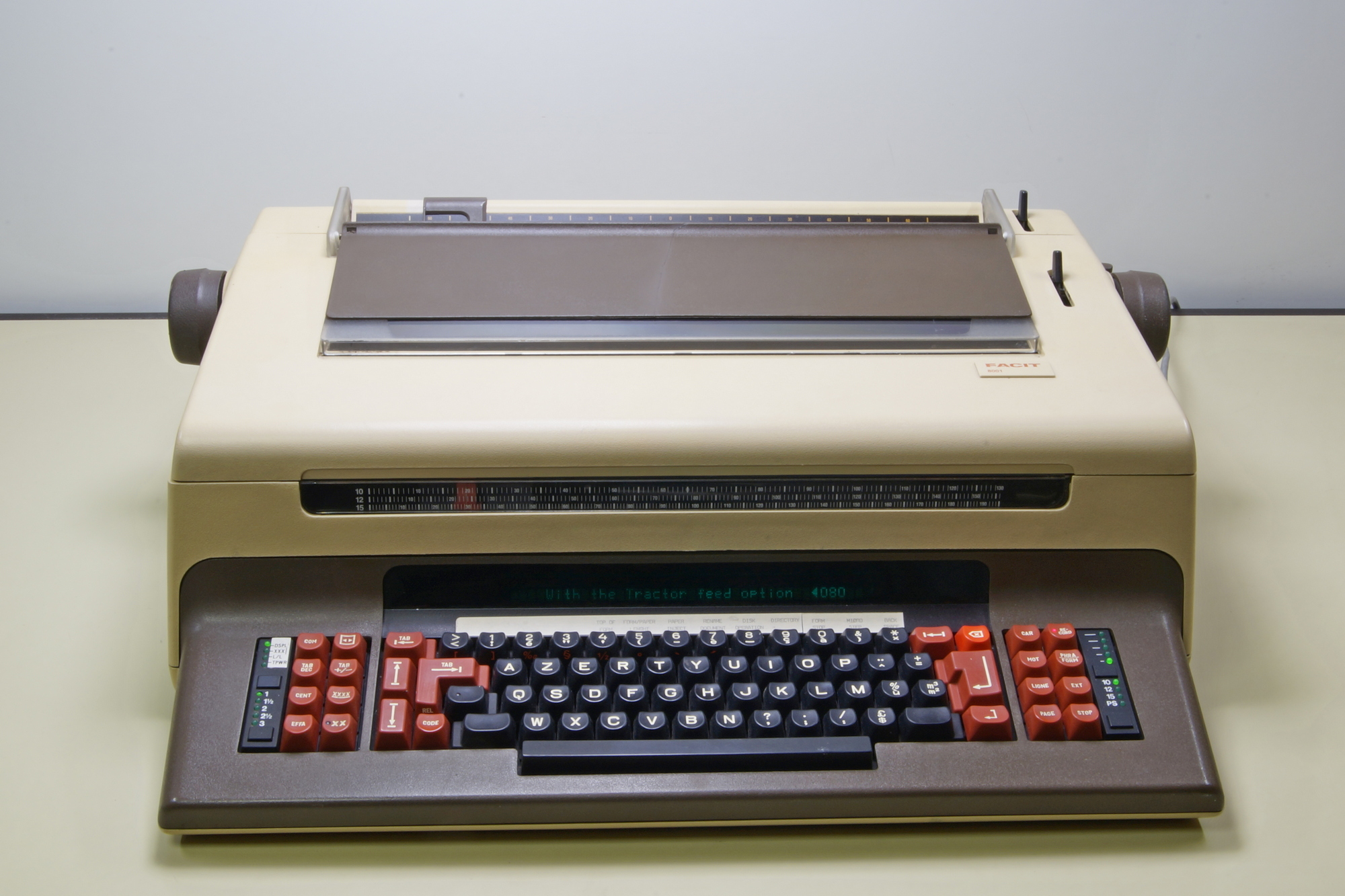
With tractor feed knobs.
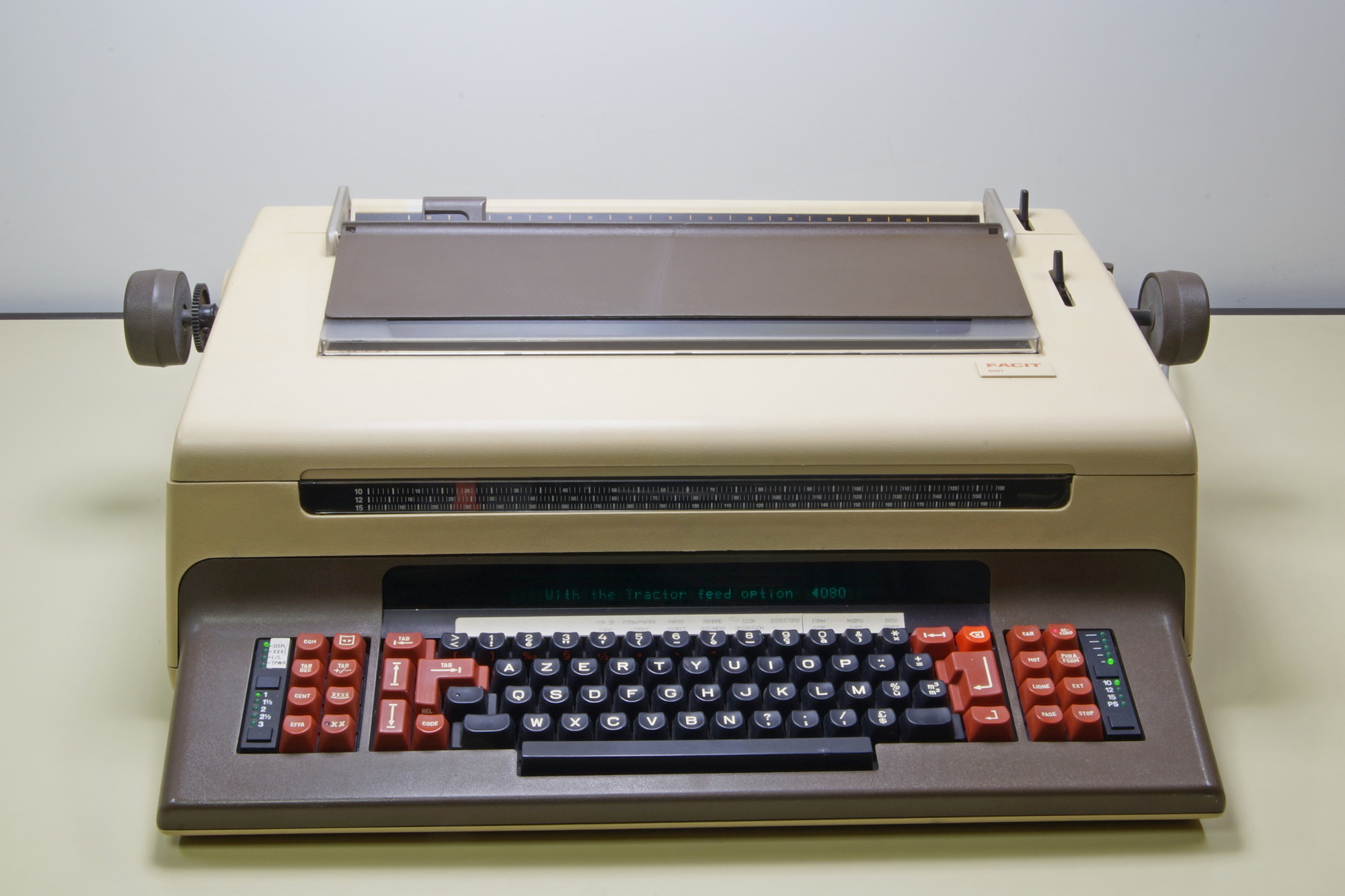
Tractor feed installed.
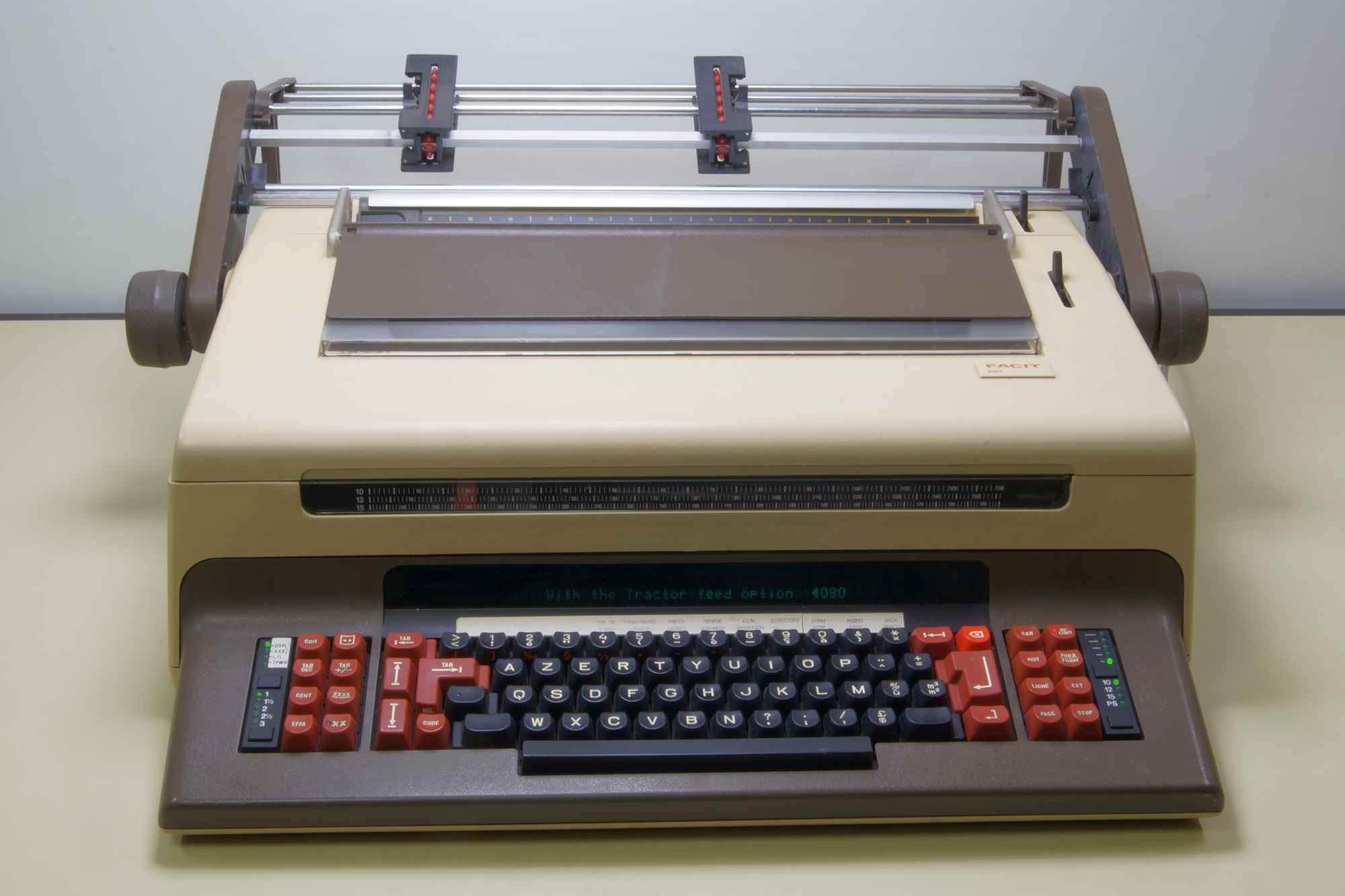
With paper holders open, ready to feed the paper.
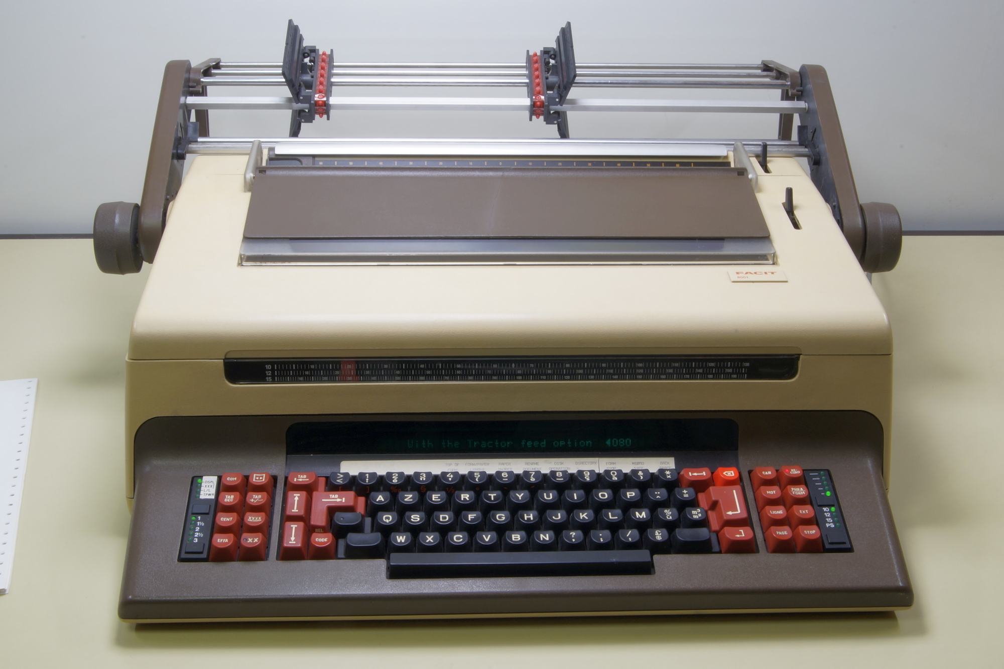
Paper in place, paper holders closed but holders unlocked, and paper end bail locked up.
The paper can now be moved left or right to adjust the printing position.
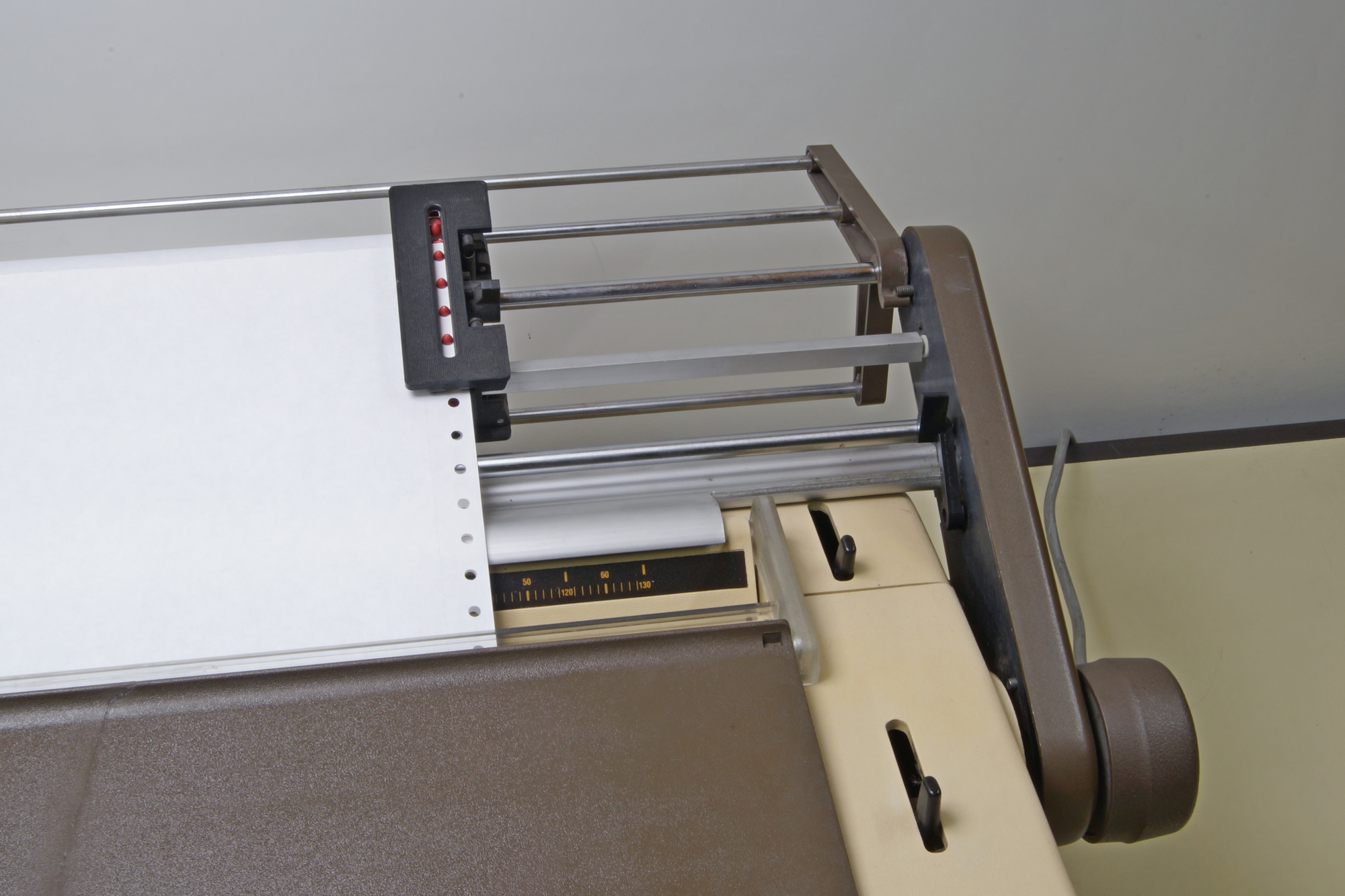
Now, the paper holders are locked, and the paper end bail is lowered, tensioning the paper.
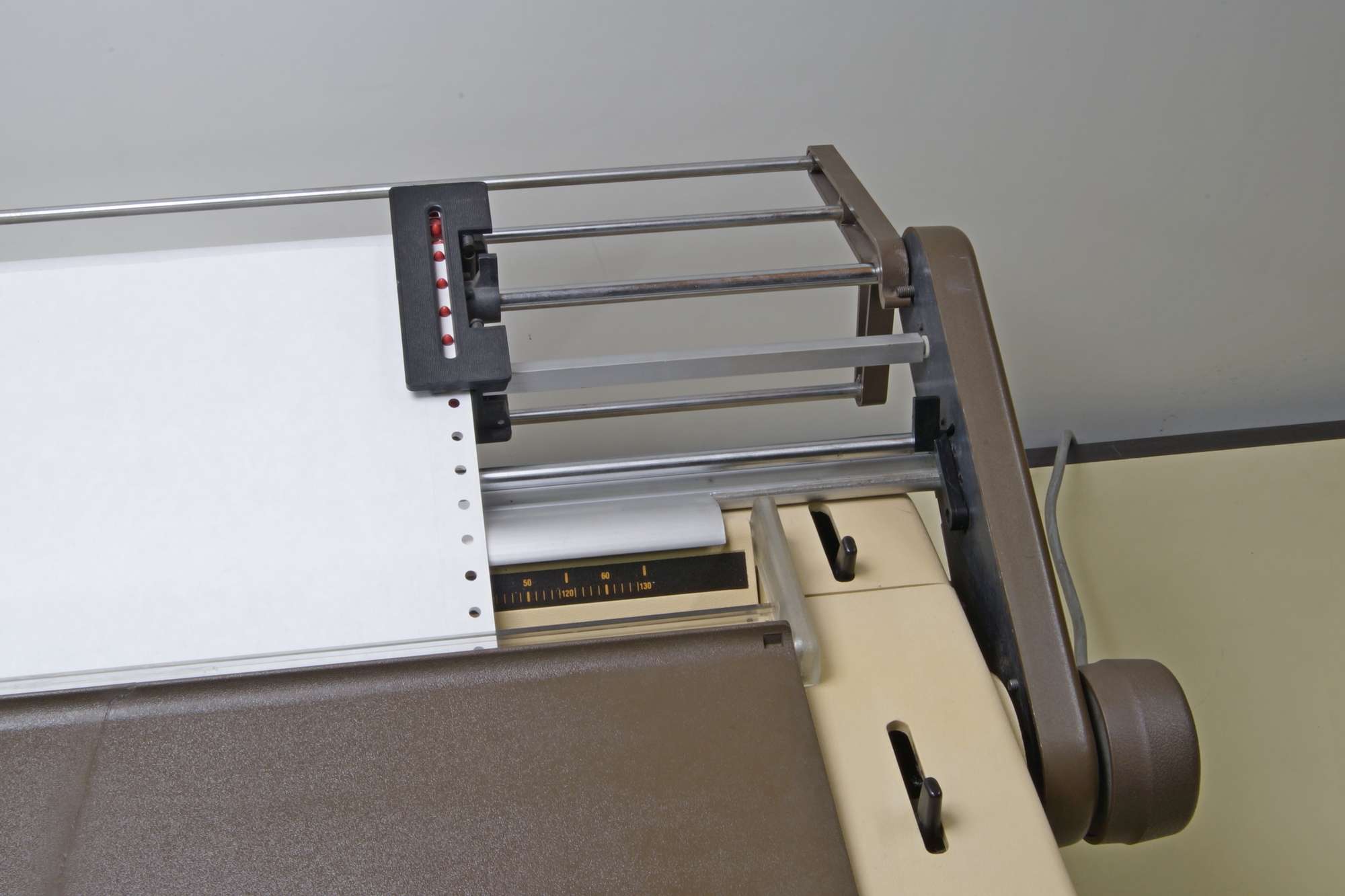
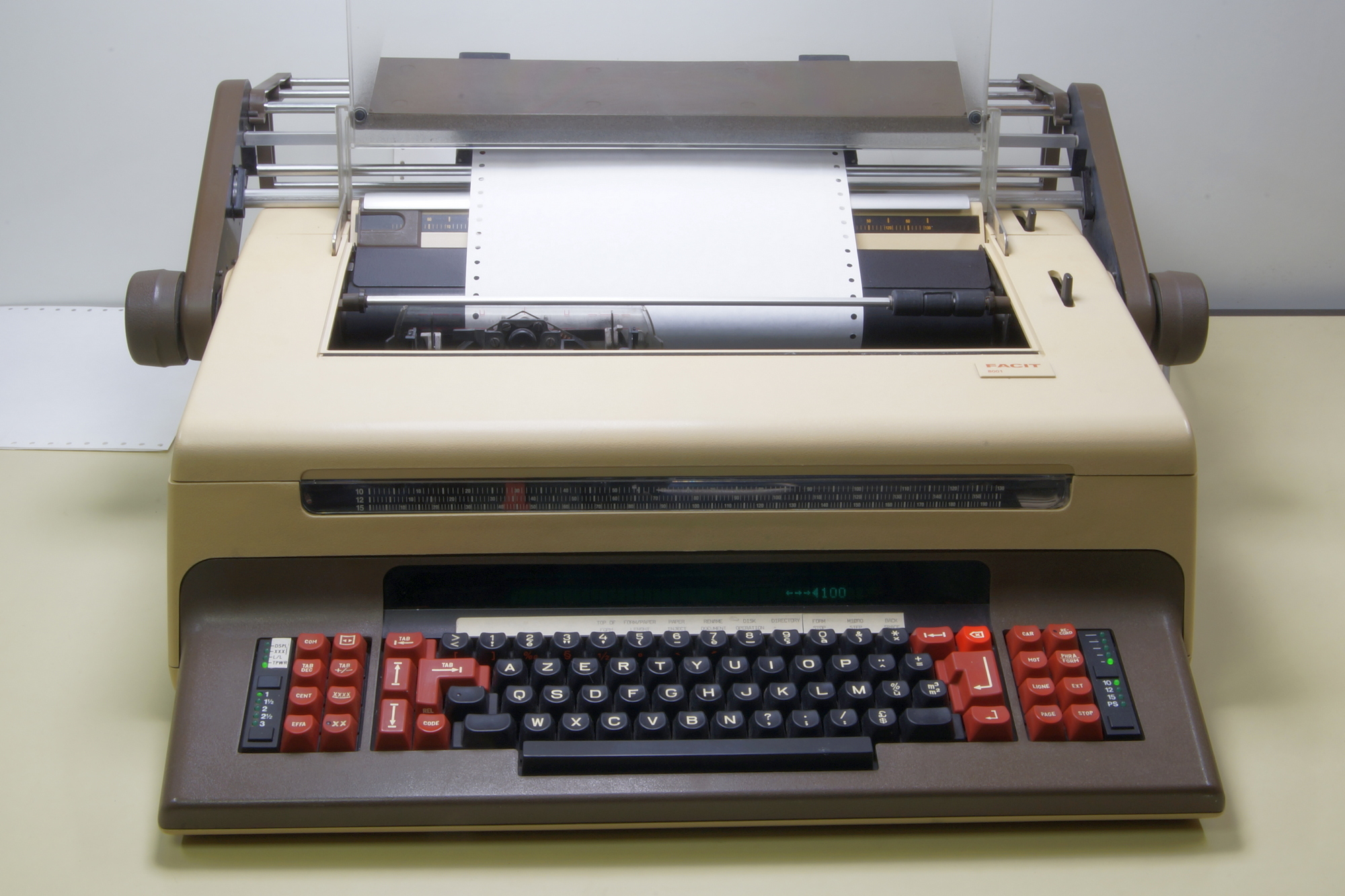
As printer, the right position was the left side, WYSIWYG was almost unknown then. Sending a margin was possible but reducing the number of printable characters. The standard was 8 inches, pitch 10 = 80 characters per line.
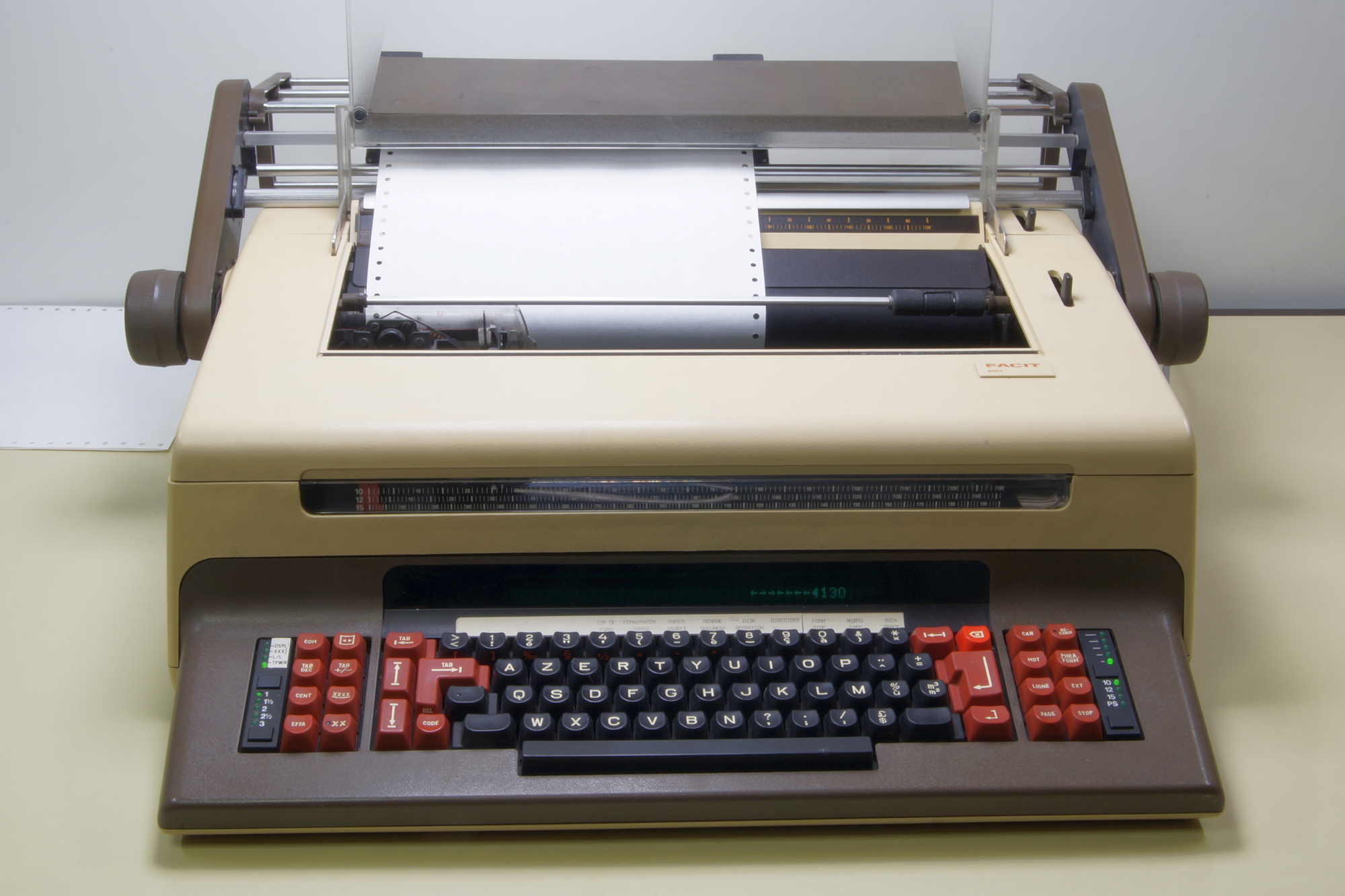
As TPWR, no problem, just use the space to the first printing position and press the margin knob (here is only one knob, the right margin is Code+Margin, on the right of the COM knob).
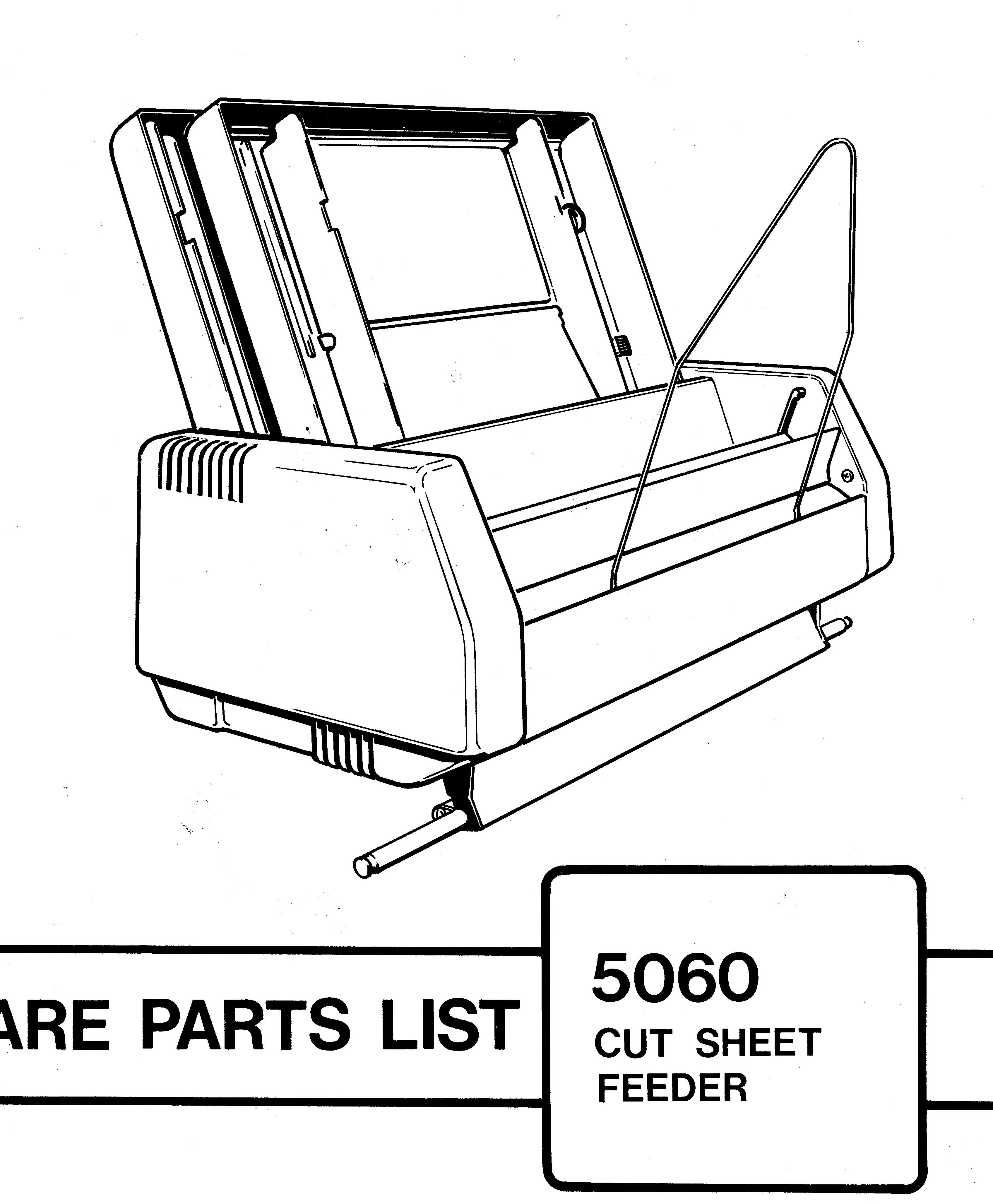
A double bin cut sheet feed was also as option, with electronic control and DC motor paper feed.
The print wheel in its box.
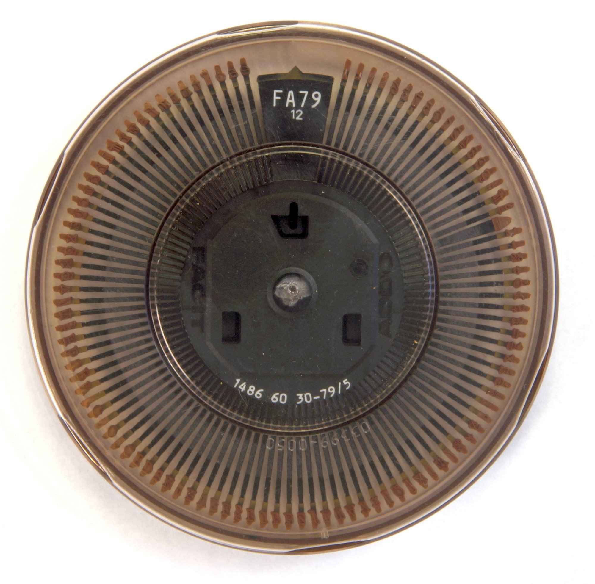
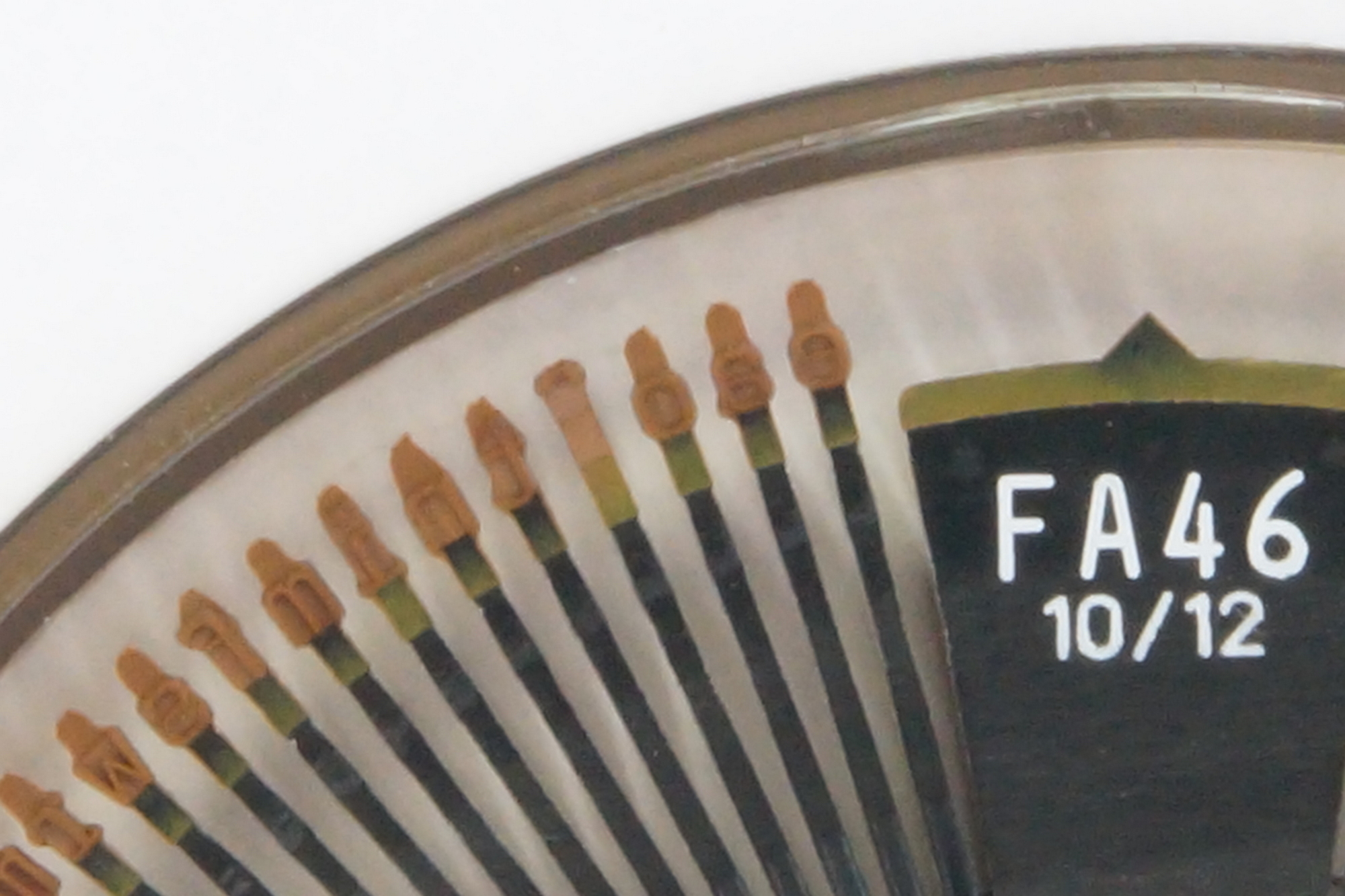
Several type styles with the reference FAxxx (FA for Facit-Addo).
46 with recommended pitch 10 or 12 (80 or 96 characters on an 8-inch-wide paper).
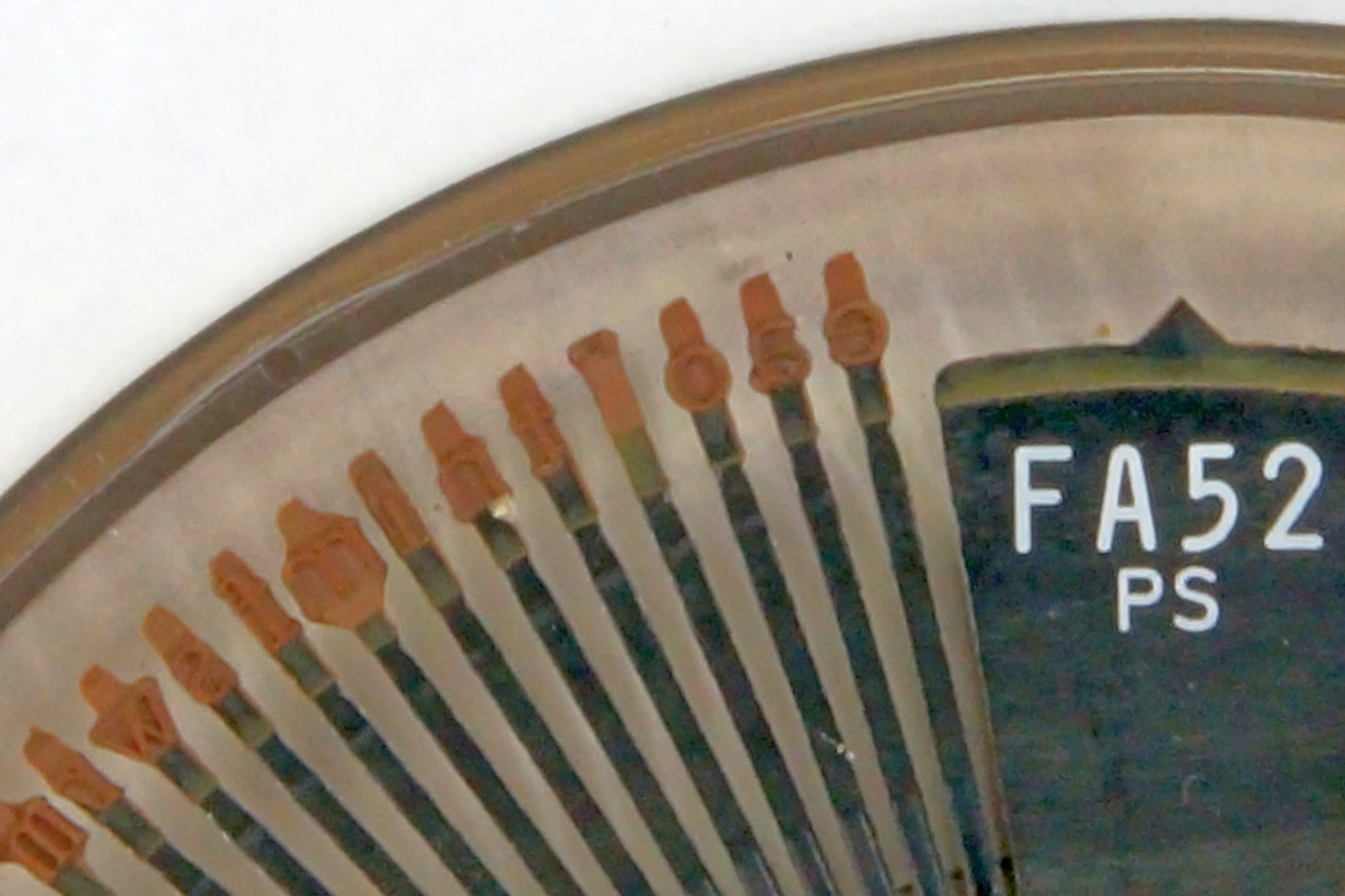
52 with pitch PS = Proportional spacing, the number of micro-steps spacing is depending of the character. Look at the difference between o, a e and m and w.
8 character styles.
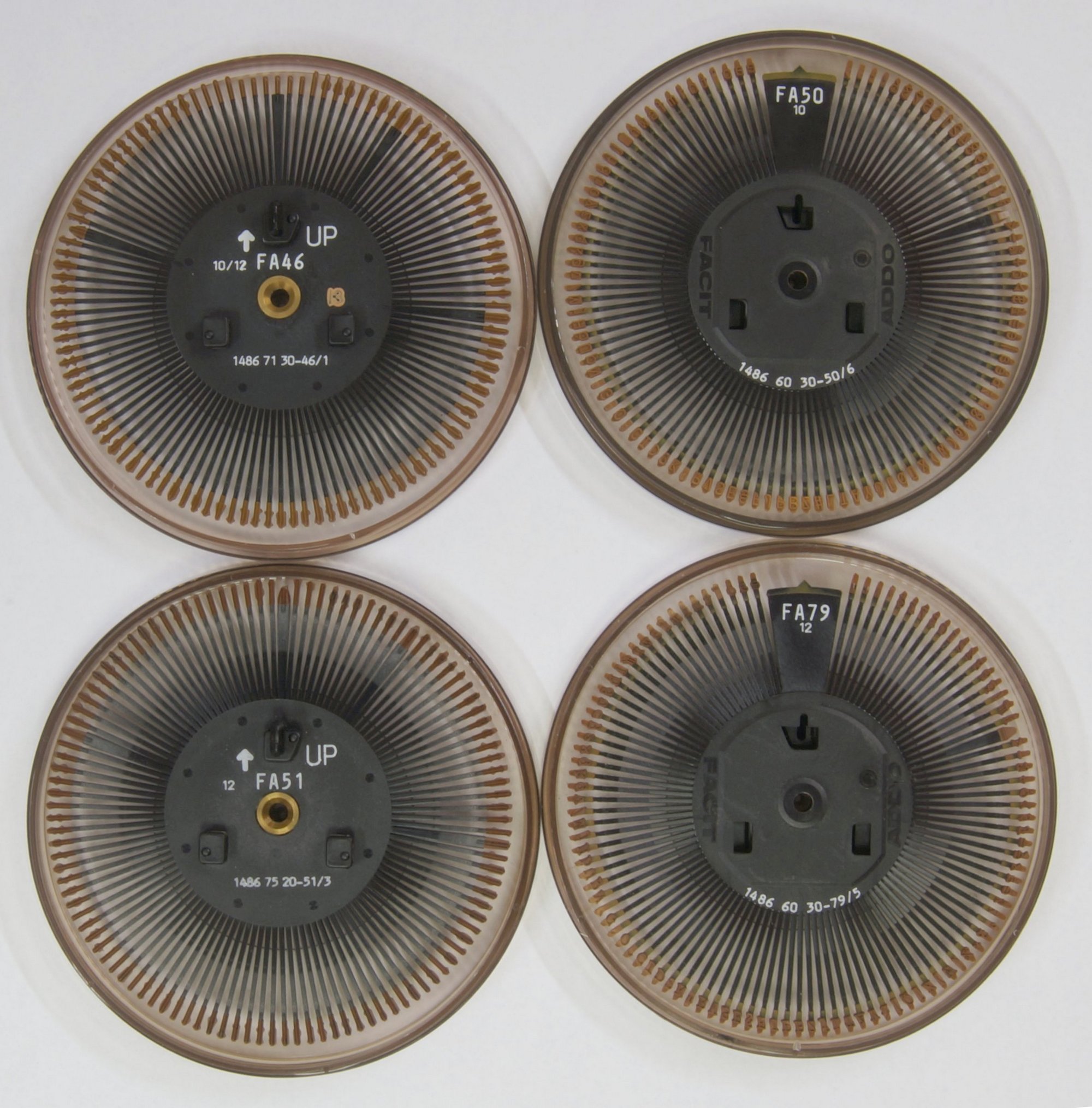
4 more ! How many fonts do you really use on your computer ???
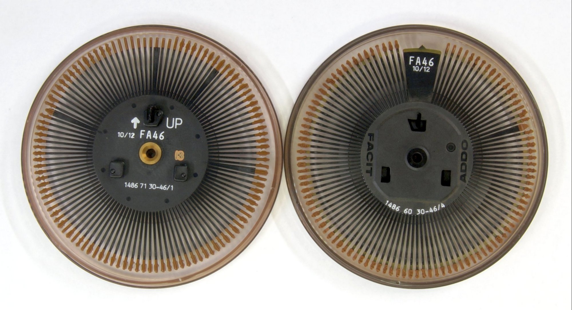
2 printwheels 46, the right one was the original, later, they replaced the upper part by 7 extra characters, making a printwheel with 112 characters in place of 105.
This was the beginning, only one new character is added, | making possible to draw a vertical line or in conjunction with the underline, a box without interruption.
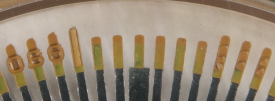
This one has already 112 characters, it’s a German language ! see the 6th character .
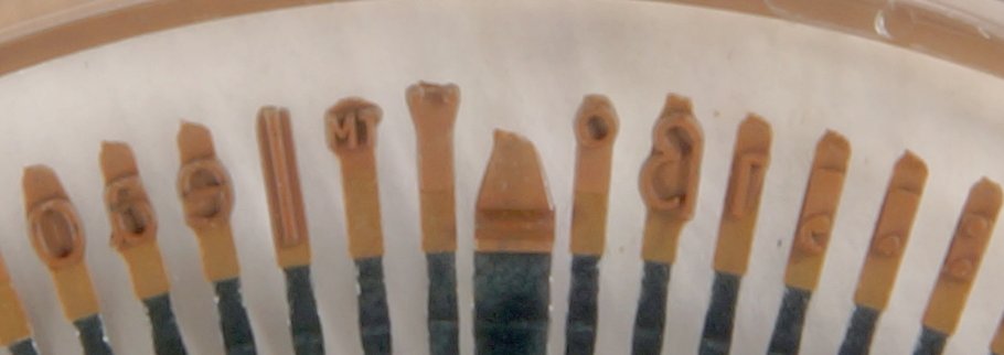
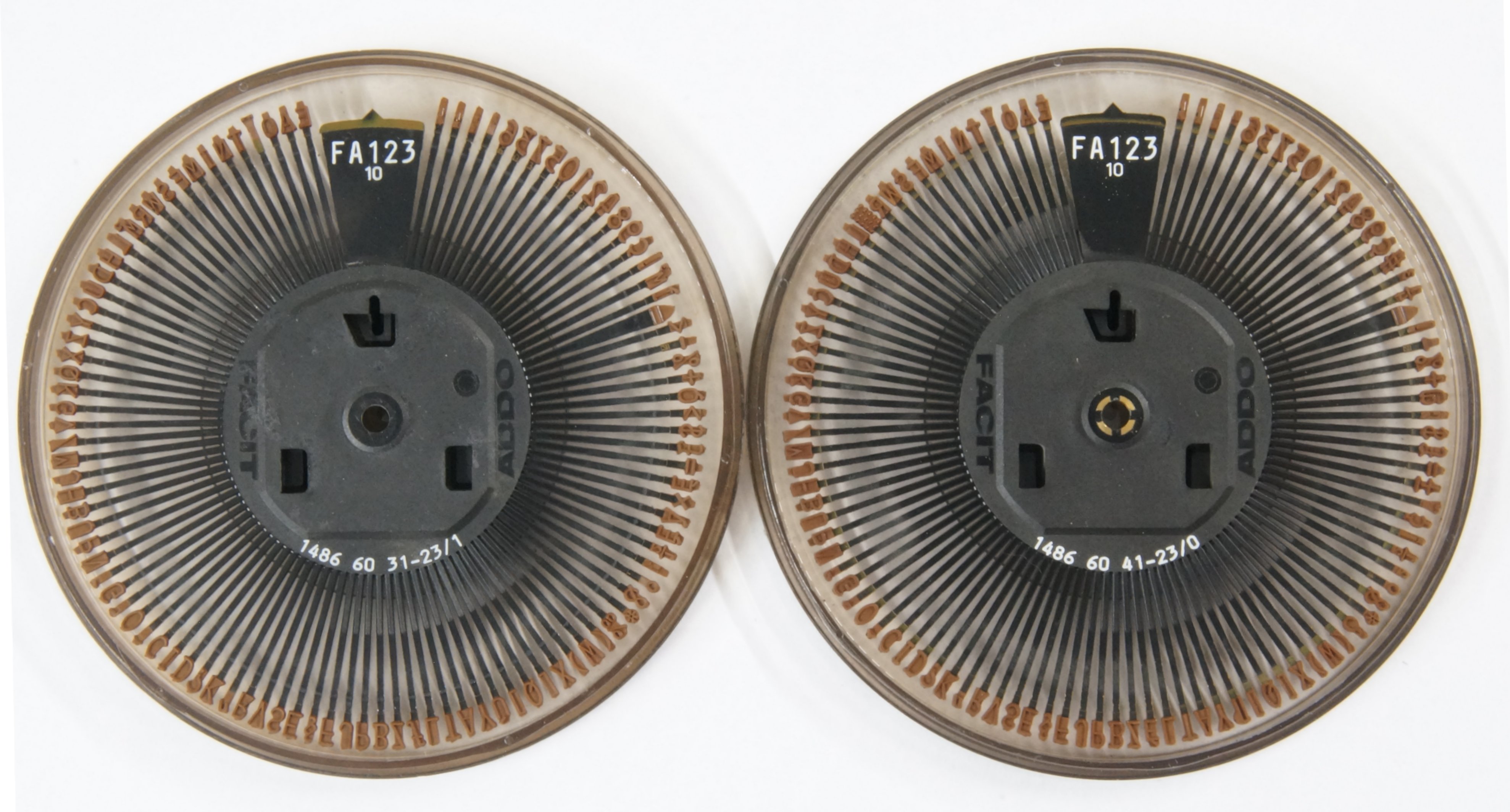
Two prinwheels 123, on the left, 603 for the French language, on the right 604 for the English language, find the differences.
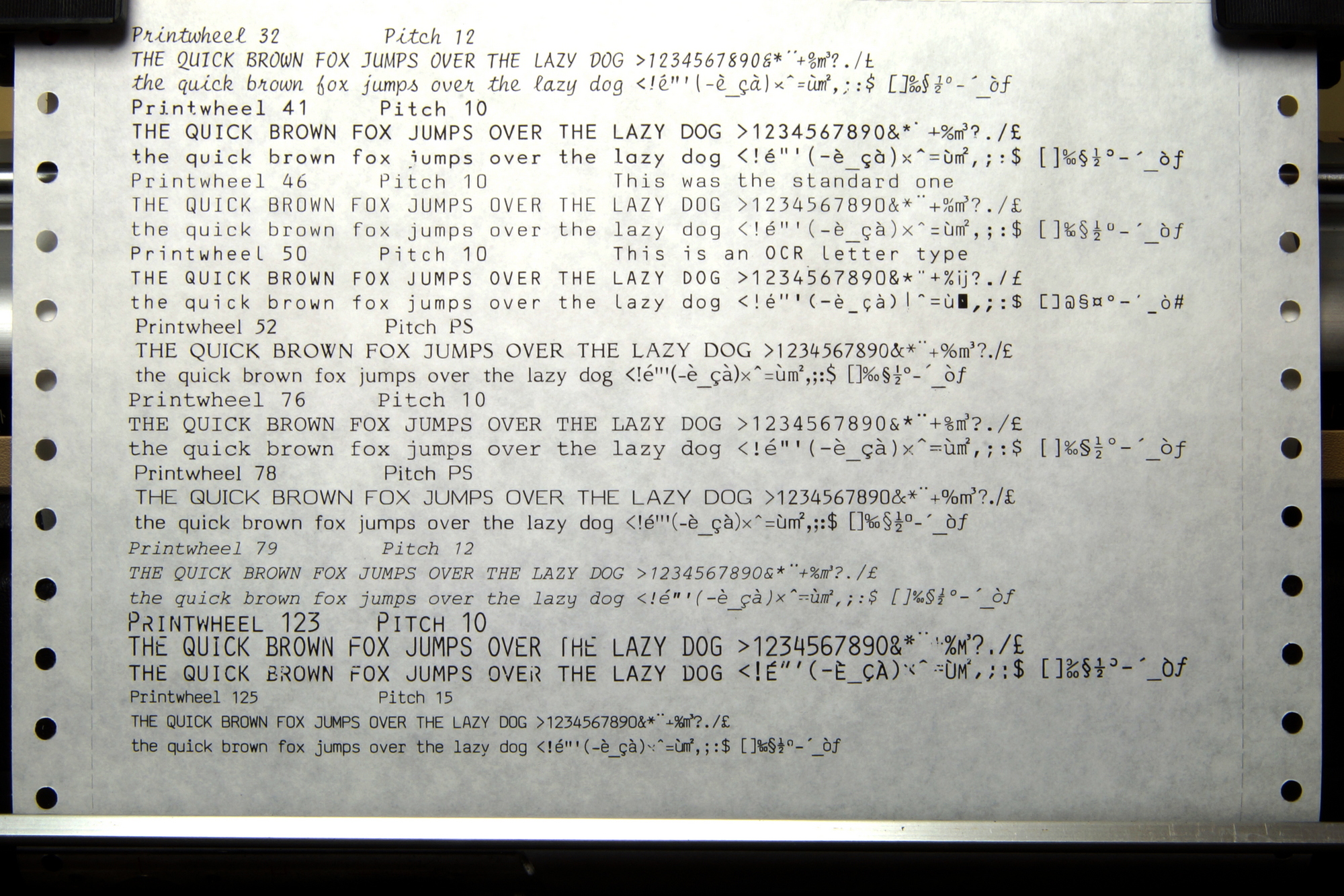
The different printing styles.
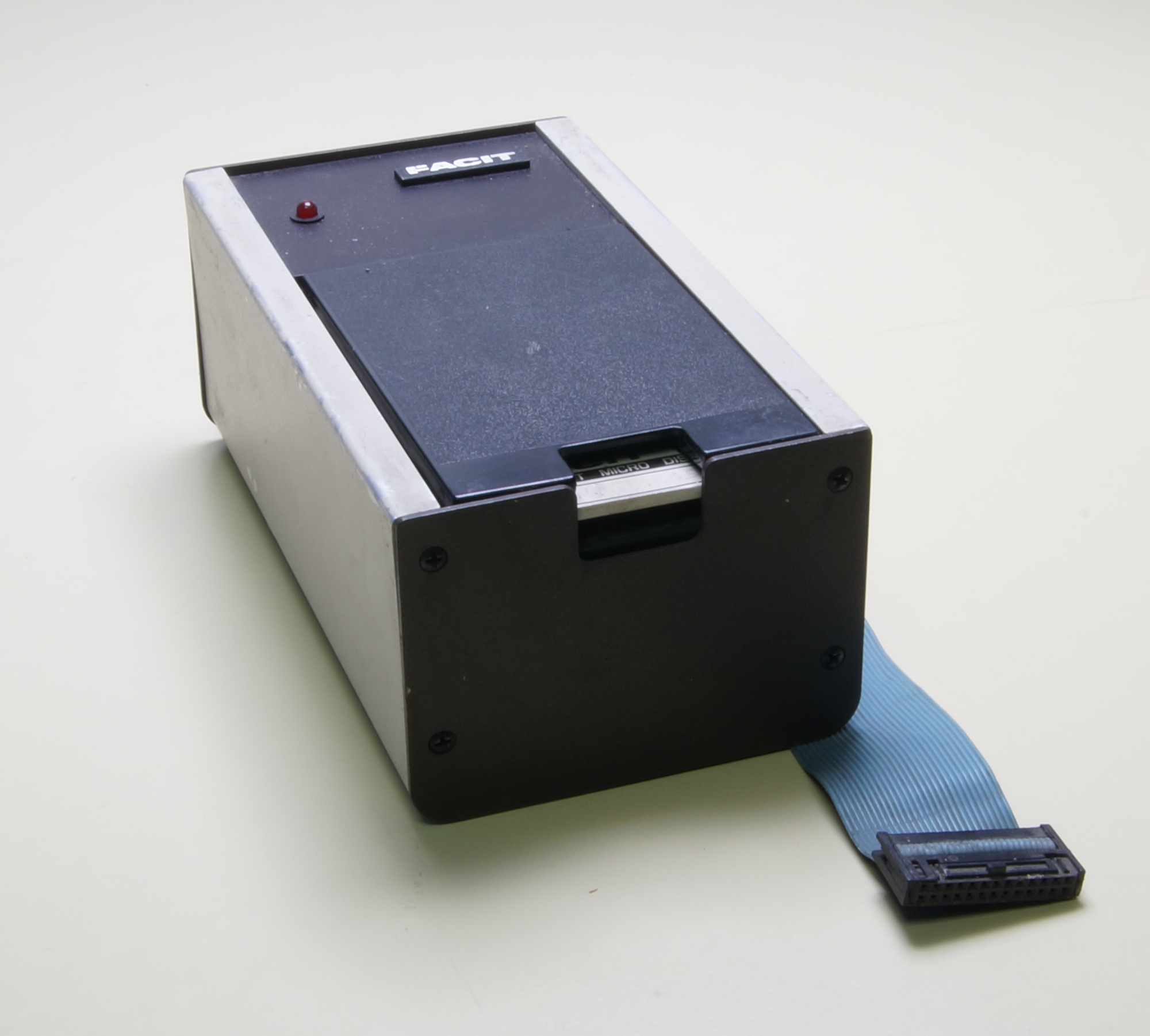
A latest option, the microfloppy disk drive.
Some parts :
First, off course, the Keythority Alps SKFF.
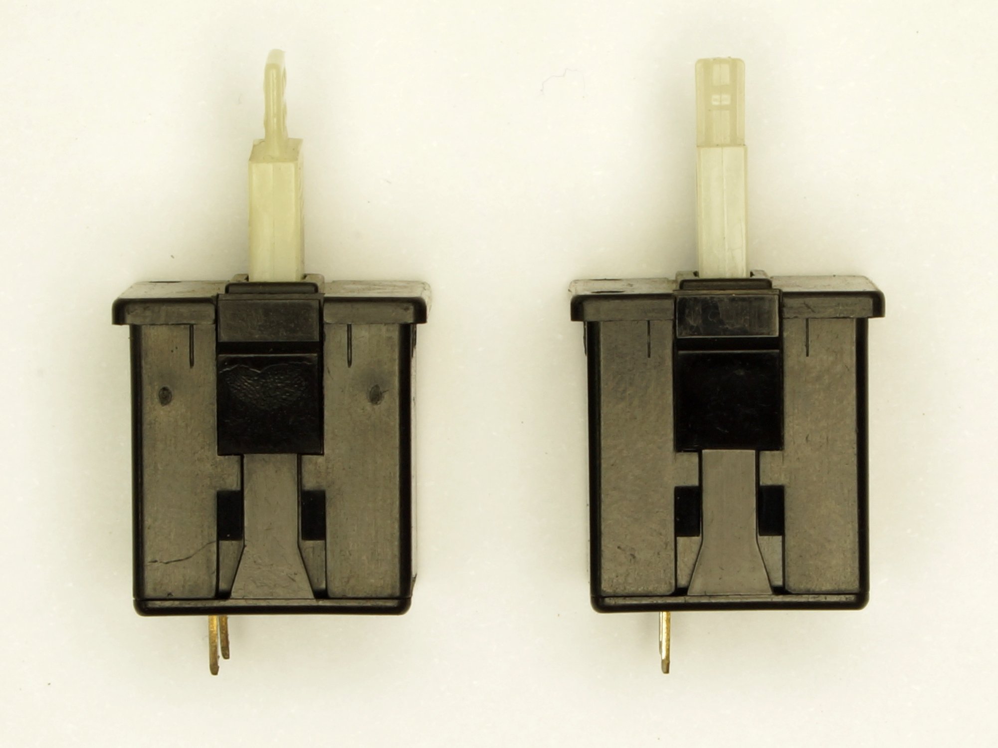
The Motors :
This TPWR series uses 3 DC motors for the main functions where almost all the other on the market were using stepper motors.
Advantages were a much higher motor torque making possible a high speed in carriage and printwheel moving without the noise of the stepper motors.
But this needed a more complicated and expensive driving section. On the control board, only two IC are needed to drive the unique stepper motor used to feed the ribbon and almost all the rest is used to control the speed and position of the 3 DC motors.
The Carriage or platen motor.
They are DC motors and are practically the same, the only difference is the chopper wheel with a different number of steps.
There are three connections,
1 - the power is connected to the left, the red and black wires.
2 – a small DC generator, called tachometer, sends a speed feedback to the control board, the yellow and orange wires.
3 – under the black cover, a chopper wheel at the end of the shaft interrupting the light barrier of an optical sensor produces pulses corresponding to one micro-step used to calculate the carriage position or the paper feed. The platen (paper feed) has no home position. For the carriage, when the power is switched on, the carriage is slowly moved to the left, when stopped by the carriage stop (rubber or ABS, see the frame higher), the direction is reversed and after a small number of micro-steps ; the home position is automatically set.
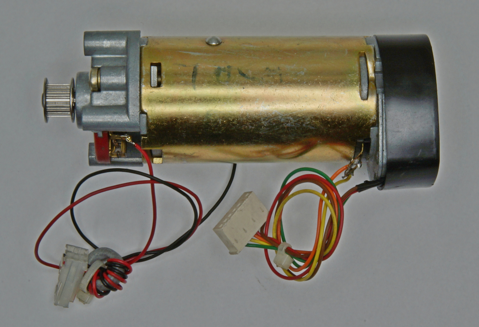
The chopper wheel,
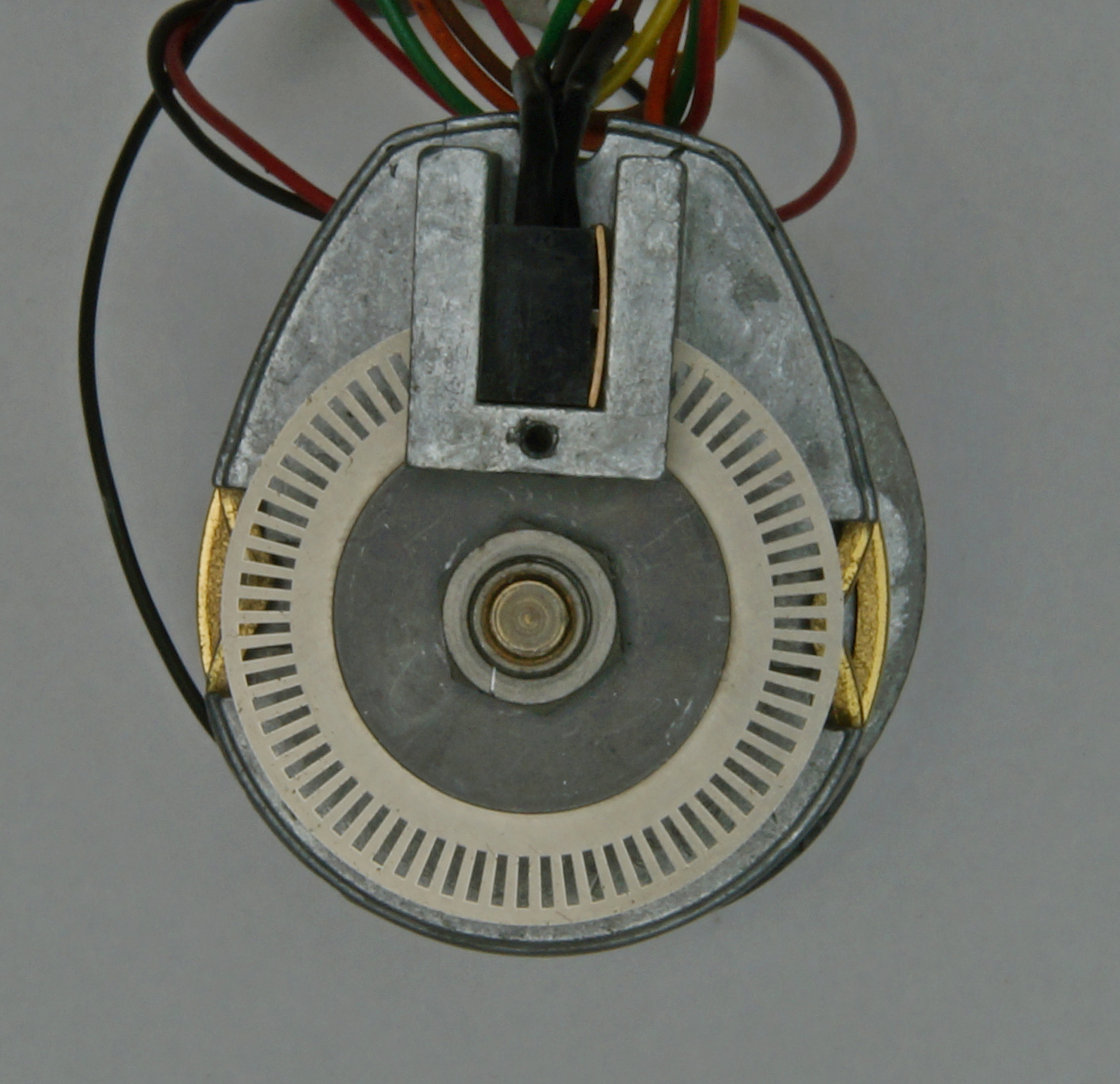
with two models of optical detectors used,
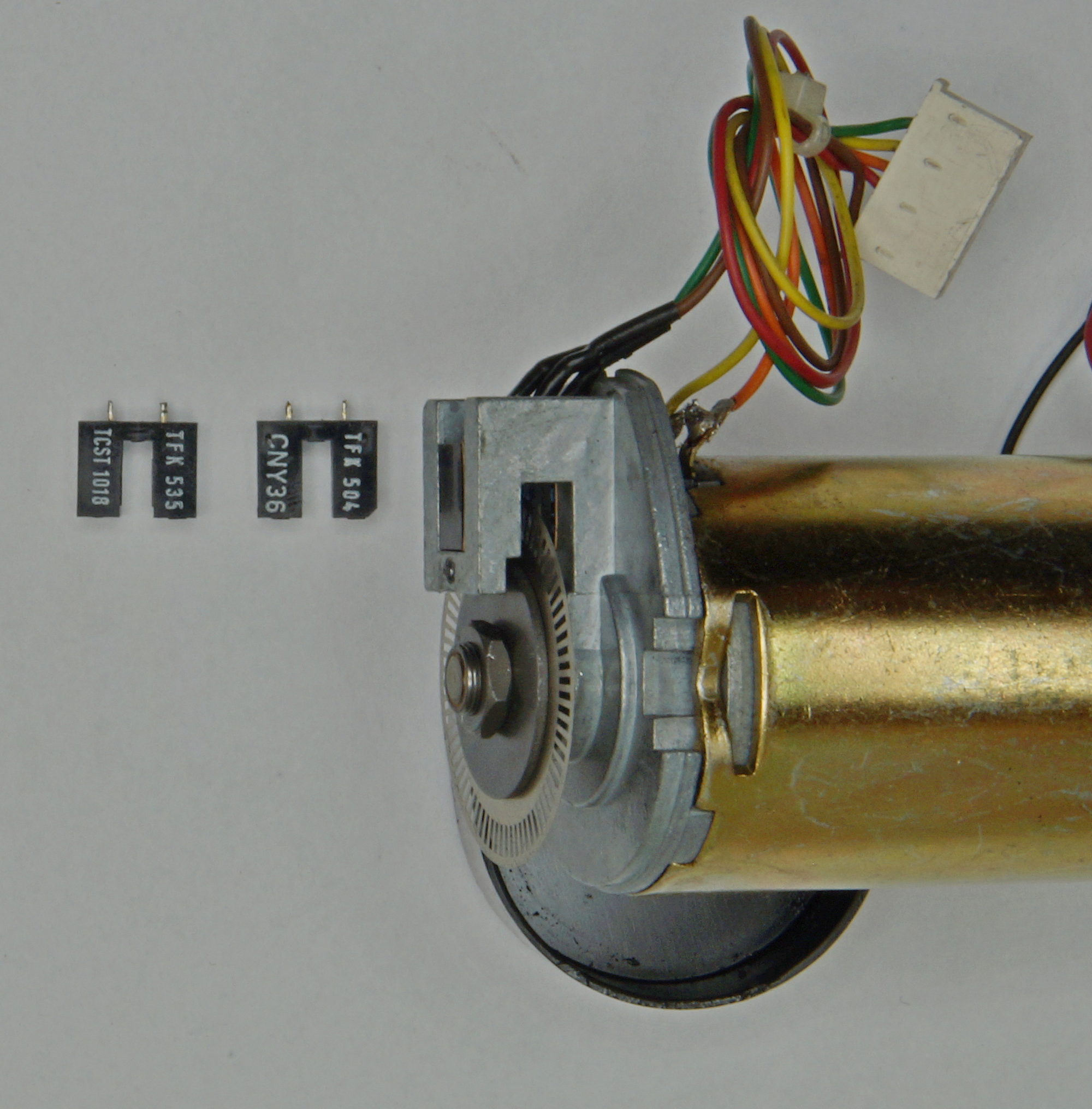
The printwheel motor.
This is also a DC motor, having the same three parts, for the position here two sensors : one producing one micro-step for each character of the print wheel and a second for the home position.
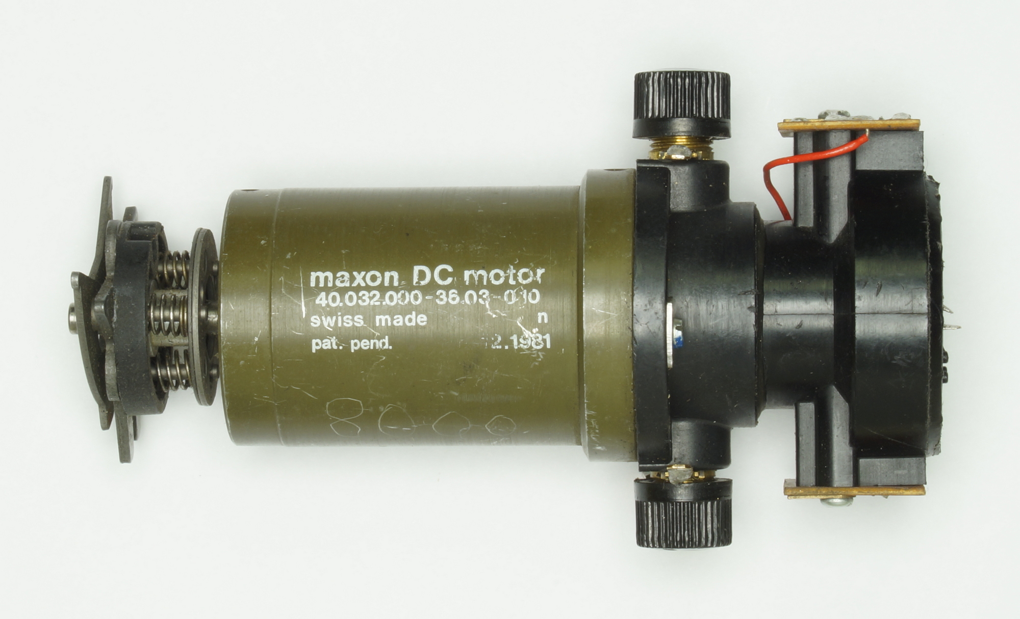
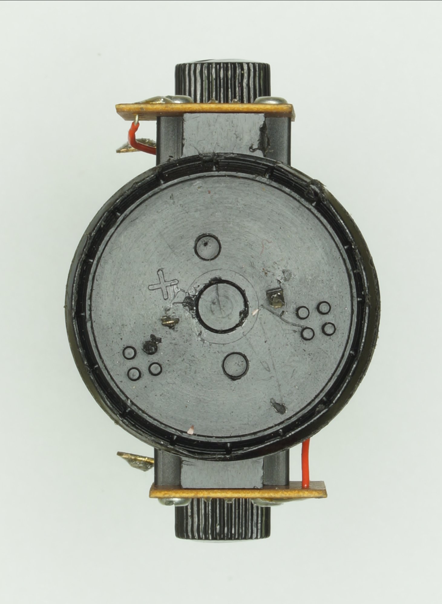
The home position sensor is the bottom one, the contacts + and – are the « brushes » from the tacho producing the speed feedback.
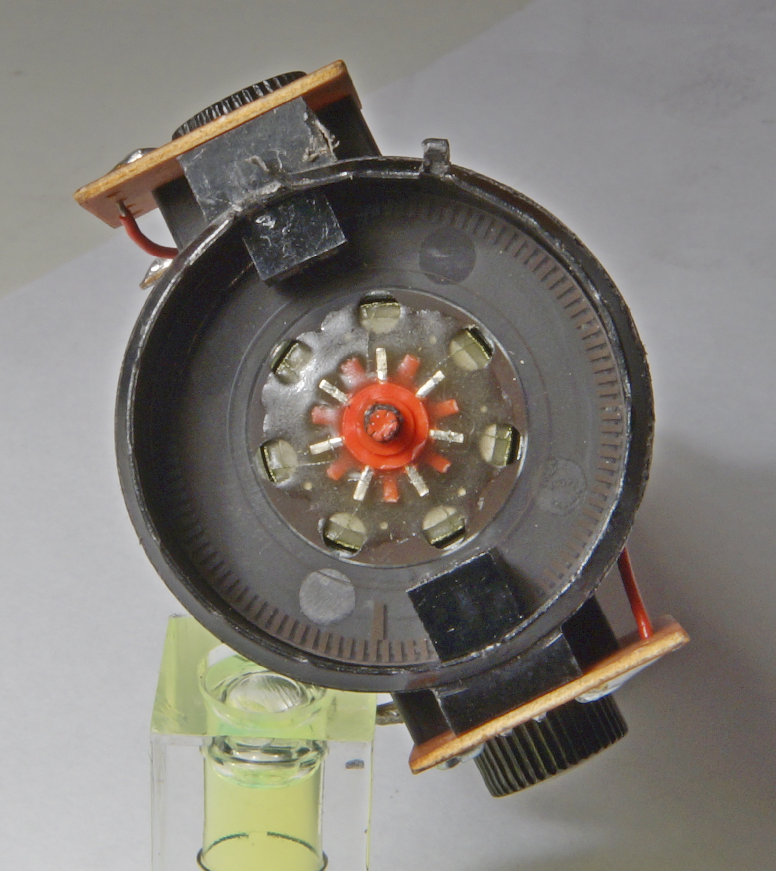
The cover with the tacho output removed to see the chopper wheel, the home position is the longer line on the left of the bottom detector, the tacho and the two optical detectors.
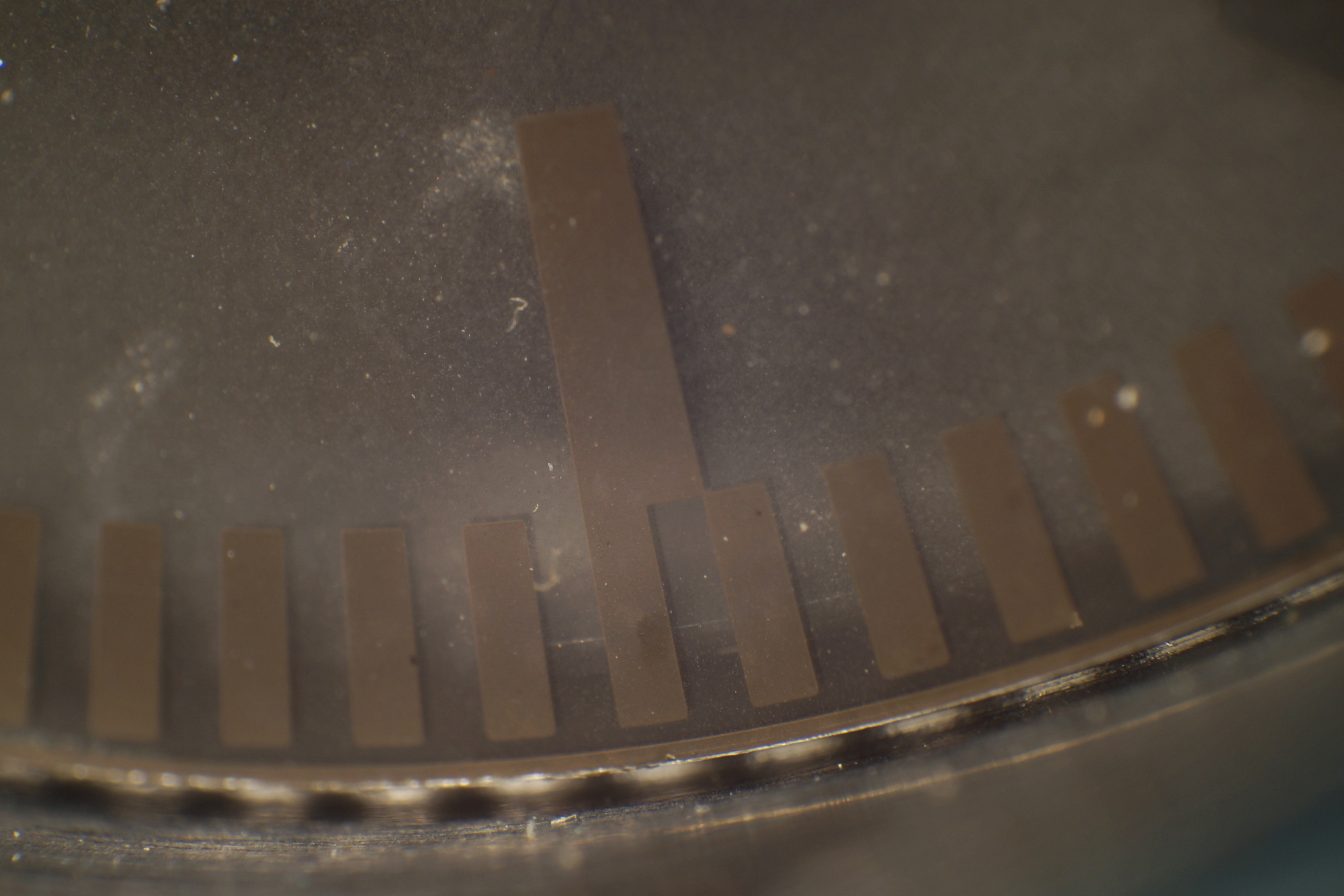
Detail of the home position on the chopper wheel.
The tachometer roughly cleaned.
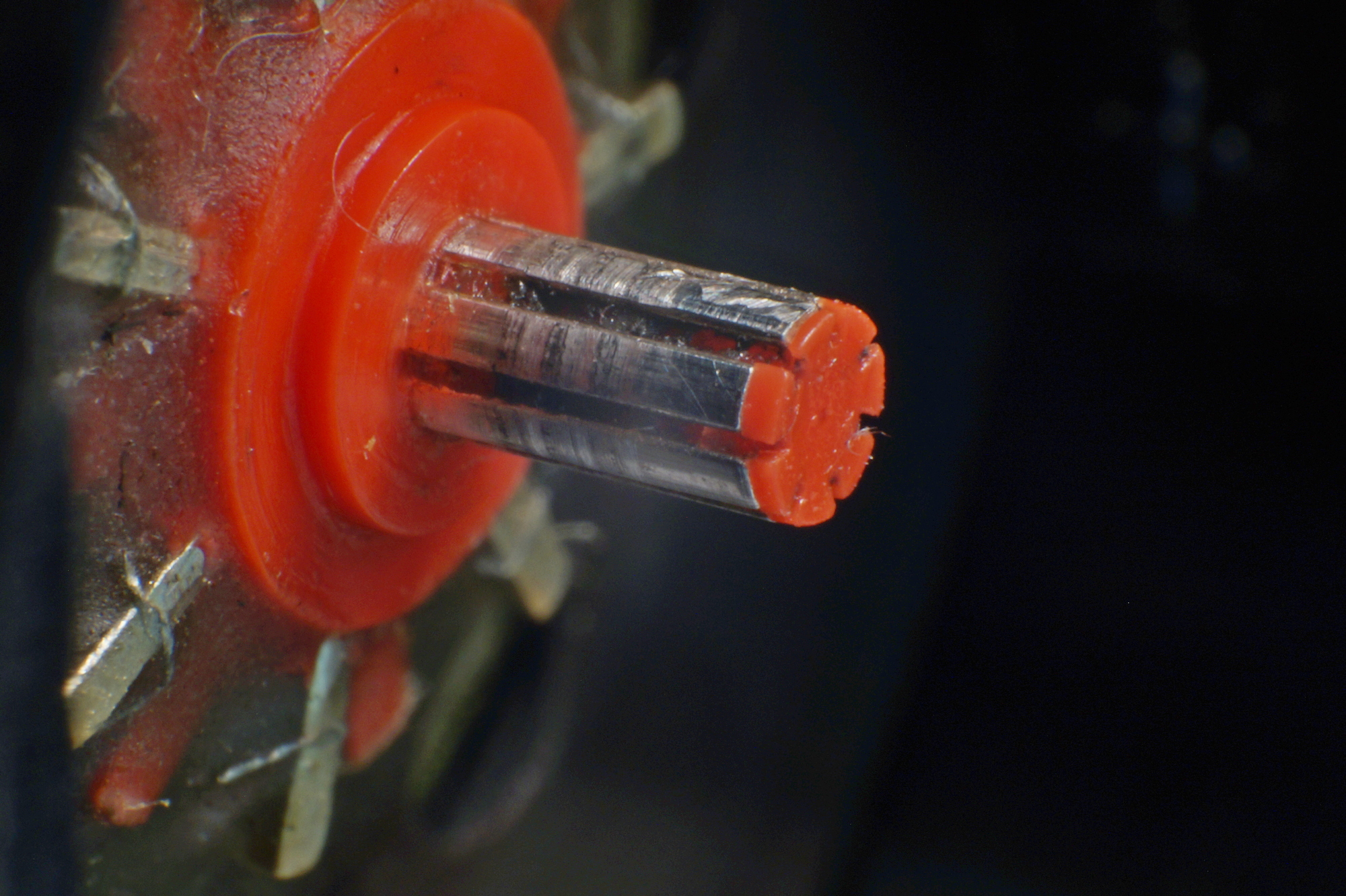
After cleaning.
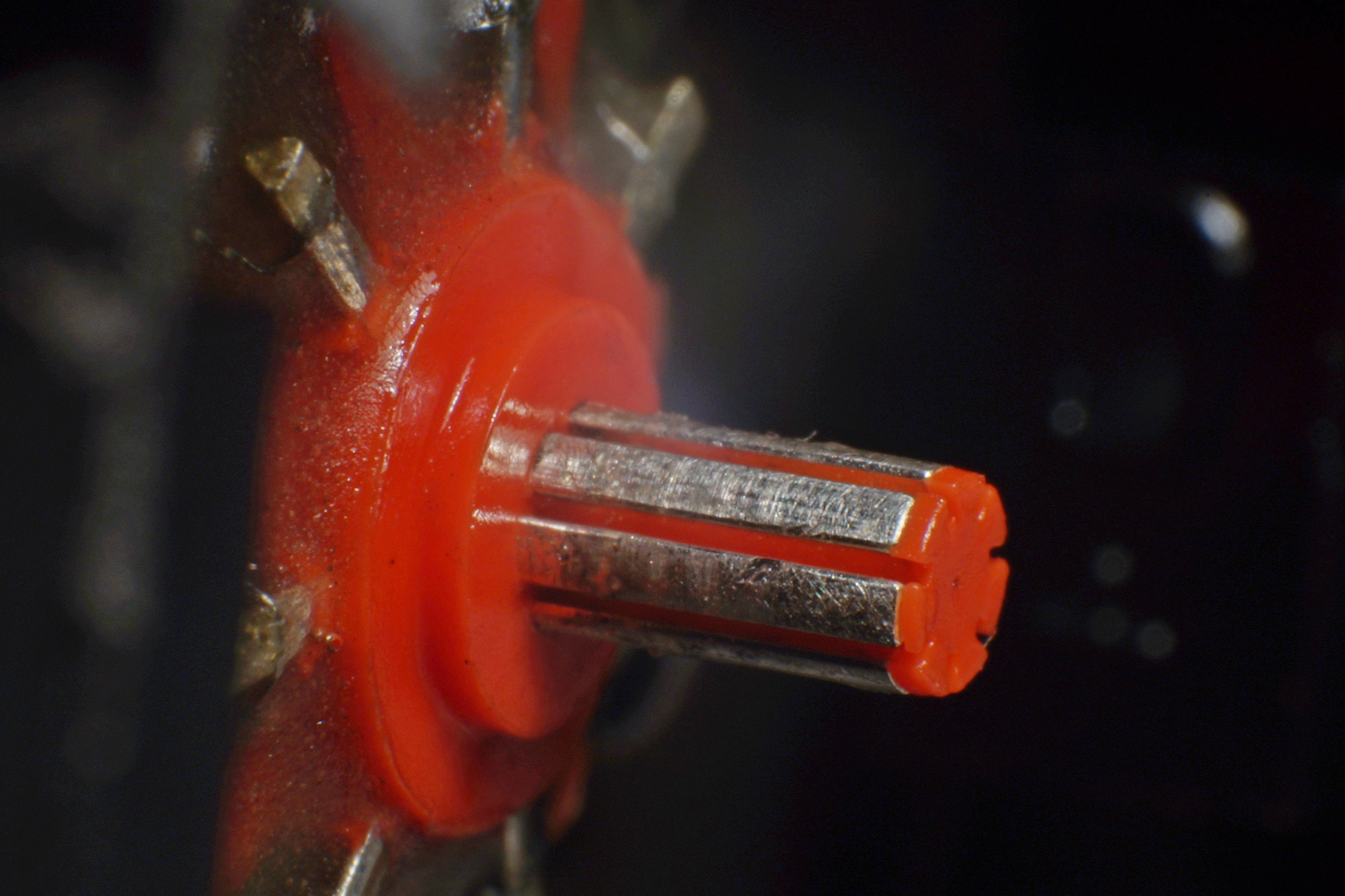
The metallic « brushes ».
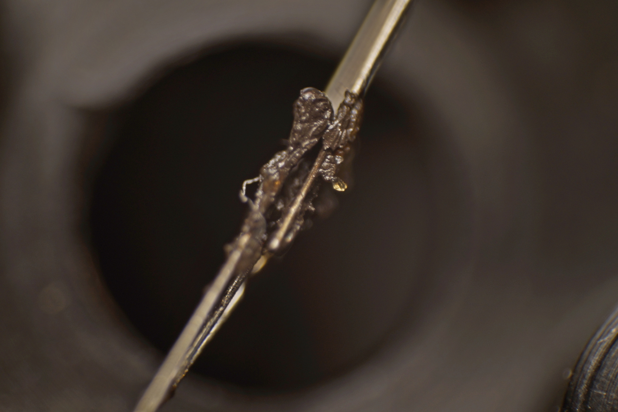
Now cleaned.
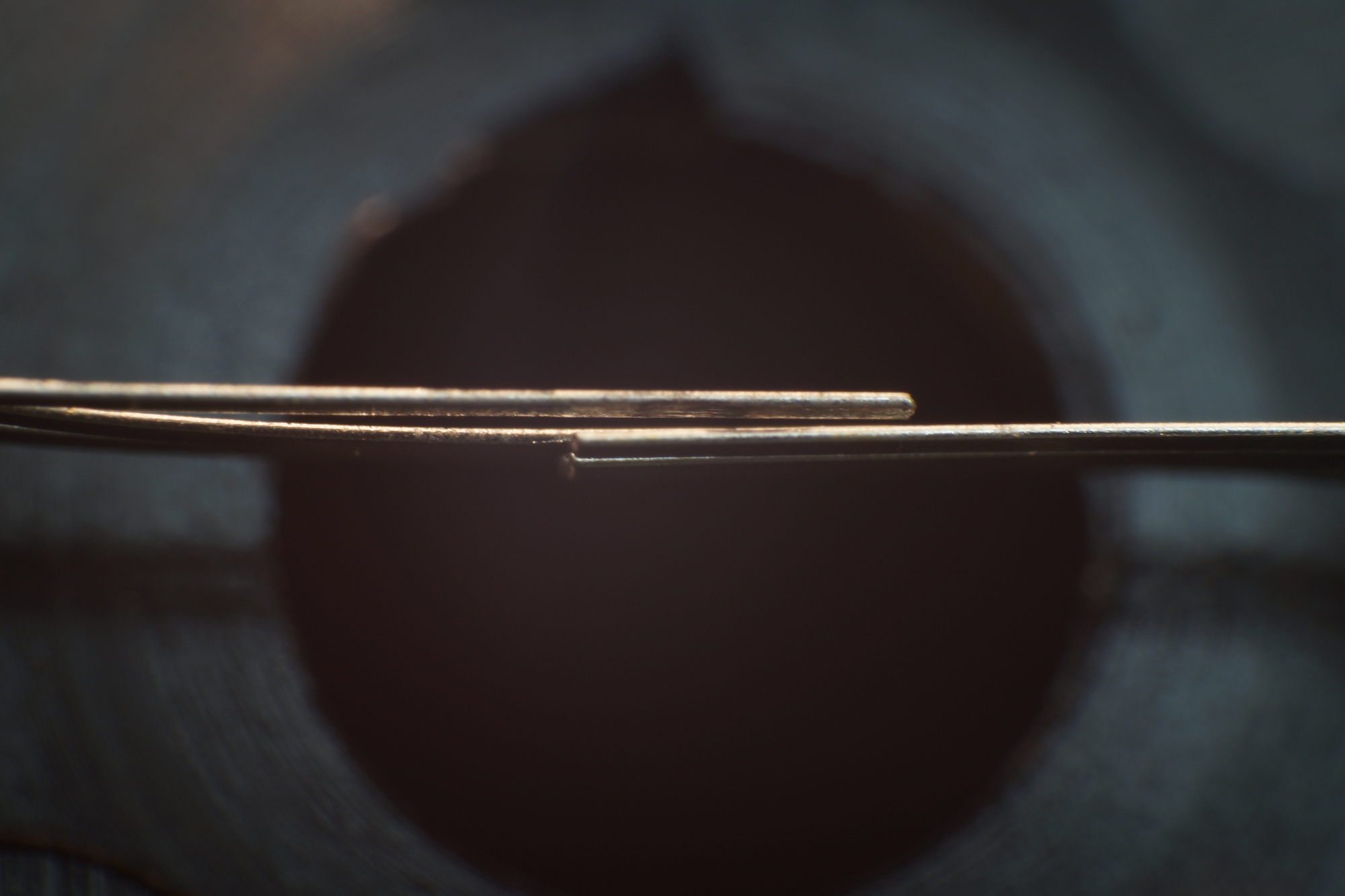
The ribbon feed motor.
The only stepper motor in the TPWR, 6V, 15°/step, 24 steps/turn.
Last edited by Facitman on 09 Sep 2018, 00:08, edited 18 times in total.
- Daniel Beardsmore
- Location: Hertfordshire, England
- Main keyboard: Filco Majestouch 1 (home)/Poker II backlit (work)
- Main mouse: MS IMO 1.1
- Favorite switch: Probably not whatever I wrote here
- DT Pro Member: -
- Contact:
I'm not sure if I'm more impressed that you actually understand this thing and can get all those tiny parts back together, or that you can light LEDs simply by the power of the Force …
- Daniel Beardsmore
- Location: Hertfordshire, England
- Main keyboard: Filco Majestouch 1 (home)/Poker II backlit (work)
- Main mouse: MS IMO 1.1
- Favorite switch: Probably not whatever I wrote here
- DT Pro Member: -
- Contact:
There's a video on YouTube of diagnosing a bad RAM chip on a BBC Micro (an 8-bit microcomputer) and it's so easy (well, once you've made the tiny little PCB that flips some address line). Nowadays, fault diagnostics is not worth it — send the whole board to some toxic dump in China and send out a replacement. Electric typewriters are insanely complicated though …
- paecific.jr
- Location: United States
- Main keyboard: IBM Model F 122
- Main mouse: Logitech Performance MX
- Favorite switch: Capacitive Buckling Springs
- DT Pro Member: -
I came expecting a few posts about the keyboard. What I got was so much better! Thank you for the detailed description and pictures!
- Facitman
- Location: Belgium
- Main keyboard: Cherry G80
- Main mouse: Microsoft Intellimouse
- Favorite switch: C.P.Clare SF5101
- DT Pro Member: -
No, that's too low. I didn't find a datasheet with the reference from the parts list, but after removing the VFD from the PCB, I could read make and model: Itron DC406A2. On the net, this gives no result, even on the japanese site of noritake-itron, VFD have a reference beginning with DN, the C could stands for customer design model.purdobol wrote: ↑What is the minimum voltage to drive that VFD screen? 12 is enough?
On the TPWR, grids & dot anodes drivers are powered by VBB=48V, the filament by 8V with a bias of 3.4V.
This bias voltage seems too low, actual models have a bias between 6 and 11V, possible that Facit chosed for more brightness what can explain my exhausted VFD.
-
- Location: United Kingdom
- Main keyboard: IBM Bigfoot + Arduino
- Main mouse: Kensington Orbit Trackball
- Favorite switch: IBM Model F buckling spring
- DT Pro Member: -
That was an amazingly detailed tear down and rebuild, with beautiful photography. One of the best I've seen on DT. Thanks for putting in so much time and effort
- Facitman
- Location: Belgium
- Main keyboard: Cherry G80
- Main mouse: Microsoft Intellimouse
- Favorite switch: C.P.Clare SF5101
- DT Pro Member: -
I can't remember the prices of all models exactly but in 1983-1986 the entry model 8001 cost about 62.000 BEF, converted in euro, +/- 1500€.
The 8121, the top model, around 2000 € without options, a little more than 30 years ago, you can easily understand this was not to find in a supermarkt .
- vometia
- irritant
- Location: Somewhere in England
- Main keyboard: Durrr-God with fancy keycaps
- Main mouse: Roccat Malarky
- Favorite switch: Avocent Thingy
- DT Pro Member: 0184
I guess that possibly manages to be less than I expected considering the sheer amount of engineering that went into it; but certainly not cheap and quite a major investment on par with the then notoriously expensive PC. I'm thinking it's in the same league as e.g. a BBC Micro model B which went for £400 plus a floppy drive, which including the controller could easily double that price, but which in total seemed to have quite a lot less engineering that went into them. I mean that typewriter just has so many bits. So many really complicated and expensive looking bits!
-
- Location: JAPAN
- Main keyboard: Model M, dodoo dome keyboard,CherryMX numeric pad
- Main mouse: logitech Master,M705 and 3 Logitech mice
- Favorite switch: ff
- DT Pro Member: -
That is great a found! Thanks for the high quality photos.
It seems you are the Facit collector. Do you know the switch on Japanese made Facit T160 teleprinter?
- Facitman
- Location: Belgium
- Main keyboard: Cherry G80
- Main mouse: Microsoft Intellimouse
- Favorite switch: C.P.Clare SF5101
- DT Pro Member: -
Unfortunately no, I only worked on the office models and only have service manuals, service bulletins & parts manuals for the 78XX, 79XX, 8XXX and 6480 series, the office machines built in Sweden. Also a few manual for the 45XX printer series.
Not sure we had manuals fot these OEM machines from the T series.
- Facitman
- Location: Belgium
- Main keyboard: Cherry G80
- Main mouse: Microsoft Intellimouse
- Favorite switch: C.P.Clare SF5101
- DT Pro Member: -
Wel, after thinking a lot and looked what backed up in my memory I beleve this was made by Nakajima and it seems it's a Nakajima AX-65 see http://www.inzercetrinec.cz/25933
- Facitman
- Location: Belgium
- Main keyboard: Cherry G80
- Main mouse: Microsoft Intellimouse
- Favorite switch: C.P.Clare SF5101
- DT Pro Member: -
Hello,
Even if I've still access to my pictures, It seems that the hosting has broken the links for this forum earlier than announced.
It's now hosted on another server
Even if I've still access to my pictures, It seems that the hosting has broken the links for this forum earlier than announced.
It's now hosted on another server
-
- Location: --
- Main keyboard: --
- Main mouse: --
- Favorite switch: --
- DT Pro Member: -
Yeah, it's a commonly rebranded model of typewriter.Facitman wrote: ↑Wel, after thinking a lot and looked what backed up in my memory I beleve this was made by Nakajima and it seems it's a Nakajima AX-65 see http://www.inzercetrinec.cz/25933
photos-f62/top-tronic-nakamija-65-typew ... t=Nakajima
- Facitman
- Location: Belgium
- Main keyboard: Cherry G80
- Main mouse: Microsoft Intellimouse
- Favorite switch: C.P.Clare SF5101
- DT Pro Member: -
Hello,
Sorry for the late answer, I didn't receive an email for the new post.
Difficult for me to answer if they were used on other makes as I was service engineer for the Belgian importer of Facit.
They were used on Facit models like 1880, 1885, 6452, 6480 and all the 8xxx series.
Sorry for the late answer, I didn't receive an email for the new post.
Difficult for me to answer if they were used on other makes as I was service engineer for the Belgian importer of Facit.
They were used on Facit models like 1880, 1885, 6452, 6480 and all the 8xxx series.