Silicon Graphics keyboard conversion

User avatar
Muirium
µ

12 Jan 2022, 12:38

So, I have this rather handsome but non-PS/2 Silicon Graphics keyboard. Good old part number 041-0136-001:
Top.jpg
Top.jpg (766.74 KiB) Viewed 21197 times
Bottom.jpg
Bottom.jpg (211.35 KiB) Viewed 21197 times
This model speaks SGI's own protocol. Quite like Apple ADB keyboards, it has no attached cable but instead a pair of identical ports on the case:

Port Exterior.jpg
Port Exterior.jpg (179.36 KiB) Viewed 21197 times
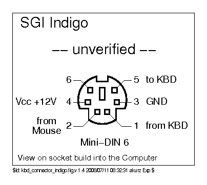
I believe they are this:

Image

12 volts? Not the most helpful thing! Here's the chip responsible: marked SGI as you can see.
Chip.jpg
Chip.jpg (226.37 KiB) Viewed 21197 times
Now, that's long put me off doing anything with it. Indeed, this keyboard's been waiting for some attention for years. Annoying, given it's aye a looker, and feels very nice indeed. Even matches my monitor and trackpad! What a tease.
Desk.jpg
Desk.jpg (518.18 KiB) Viewed 21197 times
So what to do about it? Well, first of all: the shield has to go. I peeled back its copper tabs the other night.
Shield.jpg
Shield.jpg (275.54 KiB) Viewed 21197 times
They didn't cheap out with this thing:
Shield back.jpg
Shield back.jpg (284.95 KiB) Viewed 21197 times
What lies beneath? Why, our good old friends: Alps.
Plan.jpg
Plan.jpg (754.55 KiB) Viewed 21197 times
Including an Alps original PCB:
PCB.jpg
PCB.jpg (1.11 MiB) Viewed 21197 times
This PCB looks single-sided to me. Here's a peek of the top, and what looks to be a beeper? (Indeed: it is.)
Texture.jpg
Texture.jpg (472.46 KiB) Viewed 21197 times
Where are all the diodes, though? Well, I pulled out my flashlight and sure enough: there's dozens of the wee red buggers, tucked away under the plate. Couldn't quite catch them on my phone though, so you'll have to take my word for it!
Diodes.jpg
Diodes.jpg (230.78 KiB) Viewed 21197 times
What I'm thinking, then, is the matrix looks to be all exposed for me on the single exposed side of the PCB. I'll trace it out and figure out the rows and columns. Then I need to pull the SGI controller chip, at least?

There's also the LEDs to think about:
LEDs.jpg
LEDs.jpg (218.02 KiB) Viewed 21197 times
Remember that 12 volts issue. I'll need to watch out how I drive these. I don't mind them a bit dark, fortunately. But getting them lit up from a 5 volt, let alone 3.3 volt battery / wireless controller might be tricky.

I'd also like to use these original ports for connection:
Riser.jpg
Riser.jpg (298.4 KiB) Viewed 21197 times
Much like ADB ports, they tuck into the bottom shell here:
Port.jpg
Port.jpg (133.31 KiB) Viewed 21197 times
Speaking of which, here's the manufacturer marks:
Case.jpg
Case.jpg (809.48 KiB) Viewed 21197 times
Base.jpg
Base.jpg (579.67 KiB) Viewed 21197 times
1993 top and 1994 base. Don't think my SGI had much use, given its nice condition. These damped tactile Alps are as good as it gets, in my Alpine experience:
Switch.jpg
Switch.jpg (635.16 KiB) Viewed 21197 times
And those pale Granite dyesubs are peak classy, too.
Legends.jpg
Legends.jpg (318.22 KiB) Viewed 21197 times
I'm still in two minds about doing anything destructive to this one. But if I ever want to use it, I'm gonna have to, right? For now, I'll map out the matrix and see if there's gotchas awaiting me there.
Findecanor

12 Jan 2022, 18:32

Connector pinout here. Positive and negative 8V !!
There are VR1 and VR2 printed next to what like voltage regulator circuits. The one with heat-sink has "5.0" printed on it. Most logic from that era (and USB) runs 5V.

I suspect that mouse data was just pass-through to the host, with both ports being connected in parallel. Sun did the same.
I would speculate that the +8V and -8V could be for some RS232-like interface for the mouse, with the keyboard only needing +5V.

User avatar
Muirium
µ

12 Jan 2022, 18:58

Getting there:
Matrix in progress.jpg
Matrix in progress.jpg (1.2 MiB) Viewed 21118 times
Work in progress. Haven't even gotten out the multimeter yet: this is entirely visual, from the photo above. I figured out Pixelmator is actually very well suited to this! Quite fun actually, just selective colour-filling the traces.

I'm sure several bits will join together unexpected, likes. I'll rejigger the colours when that's cleared up. But so far, it all seems fairly sensible.

User avatar
thefarside

12 Jan 2022, 22:27

Muirium wrote:
12 Jan 2022, 18:58
Getting there:

Matrix in progress.jpg

Work in progress. Haven't even gotten out the multimeter yet: this is entirely visual, from the photo above. I figured out Pixelmator is actually very well suited to this! Quite fun actually, just selective colour-filling the traces.

I'm sure several bits will join together unexpected, likes. I'll rejigger the colours when that's cleared up. But so far, it all seems fairly sensible.
Very nice! I am doing the same thing with Snag It for an Omni Key 102 and will have to try Pixelmator to see if that works better. Good luck with your project!

User avatar
Muirium
µ

12 Jan 2022, 22:45

Thanks!

I used the color fill tool. Press N to engage it. Click on a trace, and drag a little to expand it along the colour zone. When it spills like crazy, pull back a bit. Lots of trial and undo but you soon get the hang of it!

https://www.pixelmator.com/support/guid ... r-pro/1039

I should have made my traces in separate layers, as you can use lower layers for the full input. Didn’t know that at the time so did it all in one instead. The switch labels are in a layer though, so they don’t mess up my fills.

User avatar
Muirium
µ

13 Jan 2022, 13:45

Okay, I think I've got it. The multimeter confirmed my suspicion a lot of those rails do in fact continue along the keyboard, bridged by hidden connections on the other side. So here's everything re-coloured and mostly tested:
PCB with Matrix Traced.jpg
PCB with Matrix Traced.jpg (1.2 MiB) Viewed 21006 times
Which yields this 8 * 14 matrix:
Matrix Diagram.jpg
Matrix Diagram.jpg (181.27 KiB) Viewed 20998 times
The order of the rows and columns is by their pin placement on the controller. Substituting that guy for a Teensy 2++ (which I do indeed already have) is likely the big hands-on stage in this conversion. I've never tried a straight chip swap before. So I'm reluctant. But now I know the matrix, I'm more tempted than ever…
Findecanor wrote:
12 Jan 2022, 18:32
Connector pinout here. Positive and negative 8V !!
Oh, hey Fin, I never saw your post. Nice pinout. I've no idea what to do with that controller, though. Surely speaks some arcane protocol whose decipherment (and coding up a converter) are way beyond my simple skills. I'll be chuffed if I just get a USB keyboard with working lock lights out of this project. Using the beeper would be a bonus, mind. And definitely those ports for my own removable cable. I like this board's slab aesthetic.

User avatar
Muirium
µ

14 Jan 2022, 20:45

Confirmed: had the matrix almost perfect. Return and numpad Enter were off, but soon found in the handful of blank spots still available. Desoldered the SGI controller, Teensied up my own, and here I am typing on the granite right now! Always the proof of the pudding. First action this keyboard's seen this century, at least.

Just a humble Teensy 2 in here, running Soarer's Keyboard Controller and using 22 pins to drive this matrix. I had a Teensy 2++ but you need both corner pins, so there would be some jump-wires in any case. Besides, I like pushing the little guy to his limits!
Screenshot 2022-01-14 at 8.11.13 pm.jpg
Screenshot 2022-01-14 at 8.11.13 pm.jpg (154.3 KiB) Viewed 20909 times
Here's my Soarer config, matched up to all those pins, with my usual preferred Mac mods. It's rotated thanks to the diodes needing rows instead of columns to be strobed. Might be possible to rewrite it the other way, but I was keen to get on with my testing.

Code: Select all

matrix
    blocking 0

    sense               pb1         pb2         pb3         pb7         pd0         pd1         pd2         pd3
    strobe      pf1     esc         back_quote  tab         lctrl       lshift      unassigned  unassigned  lalt
    strobe      pf4     f1          1           q           a           unassigned  unassigned  unassigned  lgui
    strobe      pb0     f2          2           w           s           z           unassigned  unassigned  space
    strobe      pc7     f3          3           e           d           x           pad_8       pad_slash   pad_minus
    strobe      pc6     f4          4           r           f           c           pad_9       pad_asterix pad_plus
    strobe      pe6     f5          5           t           g           v           pad_7       pad_equals  rgui
    strobe      pd5     f6          6           y           h           b           pad_6       pad_3       pad_enter
    strobe      pd4     f7          7           u           j           n           pad_5       pad_2       pad_period
    strobe      pd7     f8          8           i           k           m           pad_4       pad_1       pad_0
    strobe      pb4     f9          9           o           l           comma       page_down   page_up     right
    strobe      pb5     pause       0           p           semicolon   period      end         up          down
    strobe      pb6     scroll_lock minus       left_brace  quote       slash       delete      home        left
    strobe      pf7     f10         equal       right_brace enter       rshift      unassigned  unassigned  ralt
    strobe      pf6     printscreen backspace   backslash   f11         f12         unassigned  insert      unassigned
end
Naturally, it's bloody dark, so no pics of my hectic handiwork. It's fair lively as you might imagine! Besides, I'd like to use those ports for USB instead of snaking an attached cable out this handsome slab. For now, it's just topless, but as we know that's not always appropriate atire, especially this dark and chilly time of year!

Does feel aye nice, this board. Next up: sourcing a male PS/2 to male USB cable…

(Those SGI ports are mini din 5, and do indeed accept male PS/2 connectors.)

zippolupan

14 Jan 2022, 21:39

That's some quality engineering! Great work there :)

User avatar
jsheradin

14 Jan 2022, 22:18

Nice project! The LEDs look like they're set up as common positive 5V by the way. Soarer's controller can handle them fine if you prefix the pin assignment with "-" so it pulls low to light them up.
Last edited by jsheradin on 15 Jan 2022, 00:05, edited 3 times in total.

User avatar
Muirium
µ

14 Jan 2022, 22:43

Nice tip. 8-)

I see the three resistors they’re tied to. The only pins I’ve hooked up are the 22 required by the matrix. Doubt I’ve still three spare! Should be able to rummage one up for Caps Lock, though. The only one which ever lights up anyway on the Mac.

Part of me even wants to give that beeper a use. Not like I listen to the one in my Kishy, but. I should know better than to treat it as a loudspeaker I could drive with a USB DAC. Well, one worth listening to at any rate. :lol:

No luck finding mini din 6 to USB cables yet. I see other pins are available, though. Anything I could trim with a simple snip? I’m no Orihalcon. True cable hacking is beyond me. But as I can assign the pins however I choose inside the keyboard, I could use something quite “nonstandard”.

User avatar
hellothere

16 Jan 2022, 17:29

Muirium wrote:
14 Jan 2022, 22:43
No luck finding mini din 6 to USB cables yet. I see other pins are available, though. Anything I could trim with a simple snip? I’m no Orihalcon. True cable hacking is beyond me. But as I can assign the pins however I choose inside the keyboard, I could use something quite “nonstandard”.
Maybe I missed something, but why not just use one of these? It's just a passive adapter, so it's not doing anything to the signals you're sending to it.

User avatar
Muirium
µ

16 Jan 2022, 17:43

Wrong USB polarity: how would I plug that into the host computer? Well, alright I guess there’s always an old USB extension cable. But it’s also quite ugly. I had one of those stuck into the board to check the port was indeed that same physical fit, and it’s most ungainly hanging out the side in plain sight. I’m picky! :lol:

User avatar
DMA

18 Jan 2022, 08:26

74 series is powered from +5V. So you seem to be correct about keyboard running at 5V and mouse probably using bipolar 8V for sort of a com port.

Re: cable - you can finally use one of those idiotic USB-cables-with-meaningless-barrel-connector for actual purpose - just have that connector-to-DIN cable, and then you'll have USB-to-DIN.

User avatar
Muirium
µ

18 Jan 2022, 13:44

I guess. I’ve never played with those before. The interconnect in the middle of the cable will weigh it down, though. As a keen lap typist, that is not desired! It’ll hang poorly in midair between me and the desk.

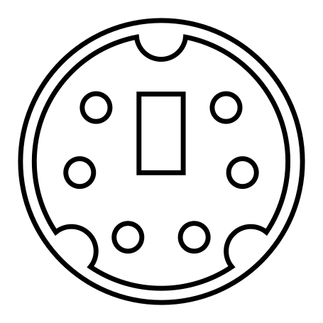
Im getting ideas, looking at these two diagrams: Mini-DIN 6 and Mini-DIN 8:
Image vs. Image

Is there anything to stop me from snipping the two extraneous pins? Why mini din 8? Because I see a fair few ready made USB cables out there like this:

Image

Providing snipped 8 to 6 does fit, the only gotcha there is where do the 4 USB pins route to: there are only 6 good answers from a possible 8. :lol:

User avatar
DMA

18 Jan 2022, 18:23

you can definitely snip those pins and the rest will match - but there's a good chance this is Yaesu programming cable so it has RS232 converter chip inside.

User avatar
Muirium
µ

19 Jan 2022, 12:11

Yeah, I eventually figured that out when I stopped browsing pics and tried to find prices. Need moar dumb in my cables! :lol:

Since I was still in the mood for matrix tracing, I decided to give my little Marquardt Mini its turn. Good grief! I'm glad I did the SGI first. This wee fella's pure mental!

Marquardt Mini Matrix clear.jpg
Marquardt Mini Matrix clear.jpg (1.37 MiB) Viewed 20546 times
Tracing that one was MUCH more work. The SGI's posh Alps PCB has higher contrast, making its traces easier to follow. I barely needed to tweak pixels at all, just working around it with colour fills was enough to paint the matrix I showed earlier.

Tried the same approach on the Marquardt, and it failed completely. Even throwing multiple pics of the PCB together as layers to enhance the contrast never cut it, though it did teach me a new skill in geometry warping to get them pixel perfect; they're all on show above. I wound up going oldschool and painting on top of the images, by hand. Well, at least the traces are all straight lines, but goodness me does the Mini take a lot of spaghetti to join its dots! Here's another view, this time with a photo of the keys in place, geometry matched for the PCB underside. I needed this to ID them at the end:

Marquardt Mini Matrix opaque.jpg
Marquardt Mini Matrix opaque.jpg (1.02 MiB) Viewed 20546 times
All that complexity for a 8×13 matrix. Huh? That many pins? It's only 83 keys so they could have done it in less, if they'd tried harder. Bet it wouldn't have been any more of a convoluted mess. :roll:

Anyway, here's the final result:

Pin order.jpg
Pin order.jpg (136.37 KiB) Viewed 20546 times
The pin labelling is my own simplistic north vs. south side of the controller, counting 1 at left to 20 on the right. There's also those three LEDs, integrated neatly into their respective keys, which I'll hook up when I do this board. It's a murderously tight wee case it's in, though, so I'll need to strategise.

User avatar
Muirium
µ

22 Jan 2022, 13:55

So, I also traced my Apple M0110 original 1984 Macintosh keyboard matrix. Actually just used jsheradin's PCB pics, as overlaid layers for contrast…

Macintosh M0110 matrix plot.jpg
Macintosh M0110 matrix plot.jpg (262.35 KiB) Viewed 20460 times

It has swirly, loopy character, but no diodes!? And, yeah, the Shifts are fused together, as are both Option keys. The result is this fairly compact, mostly 6×9 matrix:

Macintosh M0110 matrix spreadsheet.jpg
Macintosh M0110 matrix spreadsheet.jpg (177.97 KiB) Viewed 20460 times

Sure, you're really supposed to tear this out of your M0110, but I was in the mood to trace so, you know. This is my Sudoku… :roll:

As for my SGI, my next step is to rummage out a ready-stripped Mini USB cable so I can hook it up to those Mini Din 6 ports. Still need to figure out the right cable to go from those to my computer. Have I got a grey PS/2 cable to hack around here somewhere…

User avatar
Muirium
µ

29 Jan 2022, 13:11

Here's another matrix, this time my Monterey K110. Sweet little keyboard this one, but a lousy controller (with a hard coded function layer I couldn't tweak) and a heavy cable which tugs it all around the desk! Seeing as it has a nice big open port on the back (for a numpad?) I've easy access for installing a USB port of my own.
Monterey K110.jpg
Monterey K110.jpg (1.18 MiB) Viewed 20292 times
(This time I flipped the PCB images to match the keyboard’s true, user-facing orientation. There’s layers with just the bottom case etc. which give this one an X-ray vision character. I’ll make an animation sometime, as it’s fun just playing with layer visibility in the file!)

Much better designed matrix this, I will say: 8×11 for 81 keys.
Screenshot 2022-01-29 at 12.07.30 pm.jpg
Screenshot 2022-01-29 at 12.07.30 pm.jpg (71.2 KiB) Viewed 20292 times
Should be an easier project to wrap up than the SGI. But I'll get around to all of them, in time. :lol:

User avatar
snacksthecat
✶✶✶✶

06 Feb 2022, 23:58

Muirium wrote:
29 Jan 2022, 13:11
Image
This one is so cool. I'd hang a print of this on my wall.

__red__

22 Mar 2022, 23:59

Oh, I do like this kind of art!

Post Reply

Return to “Workshop”