Aegray wireless
Contents
Wireless, programmable Datahand
After having used an old dh200 for a few months, I was used to having more room to spread my hands apart with the datahands. I often type with one hand on the desk and one hand on my chest, and with the short cord between hands on the ProII, it's somewhat limiting. In addition, the limit of 20 macros was not enough. So the logical solution was to follow another project I had seen on geekhack.org ( http://geekhack.org/index.php?topic=12212.0 ) and replace the chip in the datahand with a teensy, then make it wireless.
To do this, I got the following together:
- 2 teensy++2.0 chips from http://www.pjrc.com/store/teensypp_pins.html
- 2 teensy xbee adapter boards from http://www.pjrc.com/store/xbee_adaptor.html
- 3 XBee 1mW Chip Antenna - Series 1 (802.15.4) https://www.sparkfun.com/products/8664
- 1 Arduino Mega 2560 board I had sitting around http://arduino.cc/en/Main/ArduinoBoardMega/
- 1 Arduino xbee shield https://www.sparkfun.com/products/9976
- 2 Evo External USB Battery Packs http://www.amazon.com/gp/product/B0061S10LS/
- A couple 40 pin dip sockets to remap pins on the teensy (and a couple are needed because they are easy to break) - found at https://www.sparkfun.com/products/7944
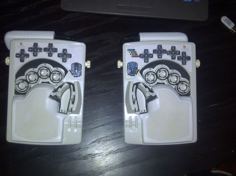
The final product looks like this:
Right hand / wiring
Each side of the datahand works by having 4 input values (called the selector) that set up a demultiplexor to output to one of 12 different lines - which correspond to a specific pair of keys. There are then two output lines that signal if its corresponding key is down - so you can read two keys at once. On the original chip, the top 4 left side pins output the "selector" value. However, on the teensy, the top left pin is ground, so the first step is to remap this pin on the board to another pin on the teensy. This is what the original project on geekhack had done.
Additionally, in order to hook up the xbee to the teensy, I needed to leave open pins d2 and d3 (the serial uart pins). On the original chip, these correspond to the location of first two key state lines, so those had to be remapped for me as well down to some pins on the input c port. I remapped things by soldering together some pins on a 40 pin dip socket, and bending up other pins on the teensy to make sure no contact was made.
On the right hand, the end result of having the chip in place looked like this:


Left hand
On the left hand, there was originally no micro controller (it just takes inputs and outputs through its connector port), so there was no simple way to plug in a teensy like there was on the right hand. After messing around with the connector for a while, I reversed out what each pin on the connector did. The following is a (rough) schematic of the connector, as seen if you were looking from the inside of the datahand towards the connector thats being plugged in (IE if you're just looking at the back of the unplugged left hand, that is backwards):
The K0-K1 are the key state outputs (inputs to the teensy), S0-S3 are selector inputs (outputs from the teensy), L0-L3 are the different leds (output from the teensy), and the other pin is the reset button on the back of the datahand (an input to the teensy). The reset button has to have a pull down resistor to ground, otherwise it will randomly fluctuate.
I currently have the left hand closed up and its harder to open because the battery pack is covering up some screws, so I don't have any pictures of the inside. But, I built a cheap connector by taking a 25 pin connector from radio shack, breaking it to be only 15 pin (8 on top, 7 on the bottom), then soldering up the wires to the correct location on another teensy I put in the left hand. This teensy was again connected to an xbee and they both fit snugly underneath the keys when the datahand is closed up - although this probably only works because I keep my keys relatively high up by default.
This connector currently just gets pinched into place by the back plastic piece, which is quite hacky. If I had wanted to take the time, it would be pretty easy to just solder the pins directly on the inside, and not require an actual connector showing. I don't have the pins / schematic currently with me for the left hand, but I could probably dig up those files if someone is interested.
PC receiver
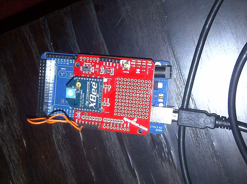
For the receiver, I used an arduino mega 2560 I had sitting around and hooked that up to an xbee. In order to make it act as a usb keyboard instead of just a usb serial port, I had to reflash the usb chip on it with some new software - details on that process can be found here: http://hunt.net.nz/users/darran/weblog/b3029/
Here is the pc receiver:
Power
For wireless power, I bought two external usb battery packs (generally used for phone charging). They have 7800mAh which provides incredibly long battery life - I forget what the draw on the teensy+xbee is but I'm guessing its <100mA. These are held in place on the back of each hand piece by extra strength velcro, and the mini usb cable goes through a hole in the back plastic piece inside to the teensy.
Notes
Overall it works pretty well. There are a few glitches from time to time with the wireless (a stuck key), especially if I'm further from the receiver, but not bad in general. Some things I would do differently if I were to start again:
- Probably use an xbee pro or xbee wired antenna for greater range and hopefully eliminate any lost packets even at bigger distances
- I could probably make this with lower cost, less parts, and less space using a chip that had wireless integrated, especially since the xbee is relatively large. I was looking at a wixel ( http://www.pololu.com/catalog/product/1336 ) however when I started out I knew a lot less about electronics and wasn't really comfortable doing that much outside of the directions I had already seen on the geekhack post. There are probably other chips like this that would work better.
Also, reading through the code and notes from the following two projects was extremely helpful in understanding how the datahands worked:


