Beam spring
 | |
| Manufacturer | IBM |
|---|---|
| Inventor |
John Robert Wolfram Richard Hunter Harris |
| Switch type | Clicky |
| Sense method | Capacitive |
| Rated lifetime | > 100M |
| Peak force | 55 cN |
| Patents |
GB1363777 (ca. 1972) US4274752 (1979) |
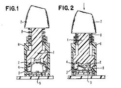
The beam spring is the name commonly given to an IBM keyswitch mechanism which was formally referred to in some documents as the combination of beam spring and fly spring or beam/fly spring interlock. It was used in almost all of the keyboards that IBM designed during the 1970s. The name refers to the beam (flat) spring in the switch that is arched upwards at rest, and subsequently inverted when pressed upon. The inversion of the spring provides the auditory feedback and tactility, as well as actuating the capacitive switching mechanism.
Contents
History
The switch was patented in 1971 by IBM, with Richard Hunter Harris and Robert John Wolfram as the inventors. Unusually, no trace remains of the US patent, and it is possible that it was rejected. The patent was successfully filed elsewhere though (a link to the UK patent is included at the bottom of the page). It replaced IBM's adaptations of the Selectric typewriter to computer use. The first keyboard to use the beam spring switch was the IBM 3277 keyboard of 1971, the last was the IBM Displaywriter of 1980. It was phased out in favor of the buckling spring which had the advantages of being cheaper, simpler and less bulky than the beam spring.
Design
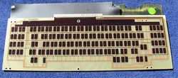
The switch uses a capacitive contact mechanism on what IBM called a "pad card" – a two layer PCB covered with an insulating substrate. On the lower layer of the pad card, there is a contact for each key on the keyboard, all of which are attached to an oscillator. On the upper layer of the pad card, there are two contacts for each key, one of which sits above the lower layer's contact, and the second is beside it, and is attached to a sensor. At the bottom of the beam spring key module is a so-called 'fly plate' – a piece of conductive plastic which sits on top of the pad card over the two contacts on the upper layer. The oscillator drives a signal on this arrangement of conductive pads, and three capacitors are formed – one between the contact on the back of the Pad Card, and the one directly above it, one between the latter contact and the fly plate, and one between the fly plate and the other contact on the top layer, which in turn is connected to a sensor. The capacitance between the lower contact and the one above it remains constant, and is used as a baseline by the sensor.
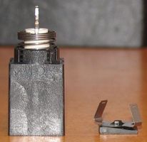
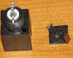
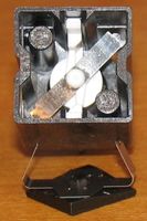
Attached to each end of the fly plate are two metal arms, each with a slot near the top (the so called 'fly spring'). A flat piece of metal with tabs on either end slots into the fly spring. The metal is tensed upwards into an arch between the two arms, consequently forming a beam spring. The midpoint of the beam spring is attached to a plunger, on the opposite end of this the keycap is attached. There is a separate coiled spring used to return the mechanism (and the keycap) to its rest position when the key is released.
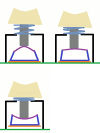
Pressing on the keycap depresses the plunger which in turn applies pressure onto the mid point of the beam spring, which flattens it. Eventually the beam spring inverts (from a dome shape to a 'u' shape) - this causes the tabs on the beam spring to push the two arms of the fly spring outwards, allowing the beam spring to pull the fly plate up. Once the fly plate is raised, the arms on the fly spring snap back into place, holding the fly plate in the raised position. Two studs inside the switch housing limit the upwards travel of the fly plate. The plunger has a rubber washer around it to absorb the force and cut down the noise of bottoming out.
As the distance has changed between the fly plate and the upper contacts, the capacitance has decreased. The sensor mechanism uses the change in capacitance to detect the movement of the fly plate, and when this occurs, the key press is registered.
Releasing the key causes the plunger to raise itself to its default position, which in turn pulls up the beam spring upwards, reverting it back to its rest position (making another audible snap in the process) which lowers the fly plate back into its rest position. The capacitance returns to its baseline level, and the keyboards ceases registering the key as being pressed.
The patent specifies that the switches had been shown to work after over 100 million key presses. The keyswitches were usually entirely covered over with a layer of insulating rubber (a contamination shield in IBM terminology), and the keycap slotted on to the mechanism over the rubber.
Specifications
The switch is roughly 5cm unpressed from the base of the housing to the tip of an installed keycap from row 3 (the asdf row). It is 4.6 cm when pressed in. It actuates roughly halfway, at roughly 4.8cm.[1]
Disassembly
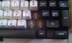
One should take care when removing the keycaps from a beam spring keyboard. The keycap's mounting slots are weak, and are prone to breakage, causing them to come loose from the switch's key stem. In some cases, the beam spring itself has been known to break. It is possible that this is a product of poor storage/heavy wear, as they are otherwise quite durable. Keycaps should preferably be removed with the aid of a keycap puller tool, pulling up slowly, and gently wiggling the keycap back and forth. It should not be pulled up straight, or wiggled from side to side.
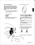
When the switch is removed from the keyboard, the fly plate can become detached quite easily. The picture gallery below details IBM's official procedure for reattaching it. However, whereas the manual recommends that the user reattach the two sides separately, it is somewhat easier to push the two sides of the beam spring so that they are caught between the two sides of the fly spring (but not attached), and then slowly pulling the fly plate down. The tension of the beam spring will usually cause its tabs to slide into the slots on the fly spring when they come into contact with each other.
IBM offered replacement beam spring key modules to customers as an FRU (Field Replaceable Unit – i.e. a component that could be replaced without returning the item to IBM) and thus Beam Spring keyboards are possibly one of the few keyboards that were designed to allow individual keys to be replaced.
Keyboards using beam springs
See IBM Beam Spring Keyboards.
Gallery
Patents
References
- ↑ Deskthority — Beam spring dimensions? Posted 2020-11-21. Retrieved 2024-04-06.
