Keyboard switch and process for production thereof
 | |
| Country | US |
|---|---|
| Patent number | 4370533 |
| Issued on | 25 January 1983 |
| Inventor |
Seisuke Kamei Hideo Nabetani Ryohei Kinoshita |
| Assignee | Fujitsu Limited |
| Reference | US4370533 |
Keyboard switch and process for production thereof is a push-button switch that is activated by the movement of the spring element of the contact plate portion of a drive rod. The invention was granted its patent number 4370533 in 1983. The assignee was Fujitsu Limited. [1]
Contents
Description
Keyboard switch and process for production thereof
- Inventor: Seisuke Kamei
- Inventor: Hideo Nabetani
- Inventor: Ryohei Kinoshita
- Patent number: 4370533
- Filing date: 5 December 1980
- Issue date: 25 January 1983
- Assigned to Fujitsu Limited
Summary
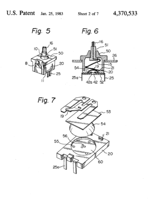
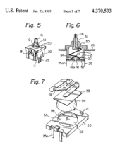
For illustrative purposes, Figure 6 summarizes the method by which the contacts open and close after depression.
The region becomes conductive only after depression of the spring element portion (17) of the drive rod (51) against the actuator (19), which in turn, presses down the top part of the dome spring (54). As a result, the dome spring (54) turns over, and closes the contacts (42)(42a) that sit in the bottom plate (52). [1]
By releasing the rod, or the key cap (not shown) which is inserted into the shaft (16), the process is reversible.
The inventors further explained that a concave shaped portion of the plate spring element (15) is preferable, since the applied force by the plate spring element (15) shifts the driving point (17a) of the element portion (17) toward the center.
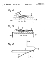
Young's modulus is 19,500 Kg/mm2. The width of the starting point (point 0 in Fig. 10) of the plate spring portion (17) is 4.1 mm, and the width of the driving point (17a) is 2.6 mm. So the portion from point 0 to the point 17a is divided into 8 equal parts and the values of coordinates x and y at each point is calculated.
| Point | x | y |
|---|---|---|
| 0 | 0 mm | 0 mm |
| 1 | 1.5 mm | 0.04 mm |
| 2 | 3.0 mm | 0.17 |
| 3 | 4.5 mm | 0.37 |
| 4 | 6.0 mm | 0.64 |
| 5 | 7.5 mm | 0.96 |
| 6 | 9.0 mm | 1.32 |
| 7 | 10.5 mm | 1.73 |
| 8 | 12 mm | 2.14 |
According to the patent, the method of fabrication is relatively easy, since the claws (11) and slits (13) are formed out of the housing (50), the notches (23) that engage the claws (11), out of the bottom plate portion (52), and the drive rod is molded by using the spring element portion.
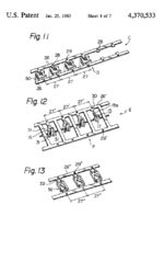
Figures 11, 12, and 13 are projected embodiments of the switch. [1]
Brief description of the drawings
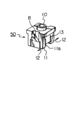
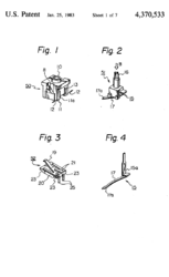
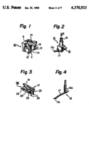
- FIG 1 is a perspective view showing a proper of the keyboard switch according to the invention.
- FIG 2 is a perspective view showing a drive rod the keyboard switch according to the present invention.
- FIG 3 is a perspective view showing a housing bottom plate of the keyboard switch according to the invention.
- FIG 4 is a perspective view showing a plate element of the keyboard switch according to the invention.
- FIG 5 is a perspective view showing the elements shown in FIGS 1 2 and 3 assembled to the keyboard switch according to the present.
- FIG 6 is a view showing the longitudinal section the central portion of the switch shown in FIG 5.
- FIG 7 is a fragmentary perspective view one embodiment of the housing bottom plate of keyboard switch according to the present invention.
- FIG 8 is a sectional view showing the state of the housing bottom plate shown in FIG 7 which the contact is opened.
- FIG 9 is a sectional view showing the state of the housing bottom plate shown in FIG 7 which the contact is closed.
- FIG 10 is a diagram illustrating the shape of the spring element of the keyboard switch according to present invention.
- FIG 11 is a perspective view showing the process forming the housing proper according to the invention of the process.
- FIG 12 is a perspective view showing the process forming the drive rod according to the present of the process.
- FIG 13 is a perspective view showing the process forming the housing bottom plate according to the invention of the process.
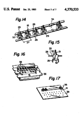
- FIG 14 is a perspective view showing the process assembling the keyboard switch according to the invention of the process.
- FIG 15 is a side view of the keyboard switch in FIG 14.
- FIG 16 is a perspective view illustrating one of the keyboard switch assembling process to the present invention.
- FIG 17 is a perspective view illustrating embodiment of the keyboard switch assembling according to the present invention.
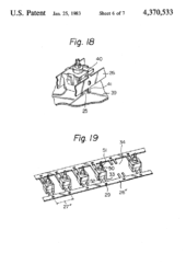
- FIG 18 is view showing parts of the keyboard shown in FIG 17 in detail.
- FIG 19 is a perspective view illustrating still embodiment of the keyboard switch assembling according to the present invention.
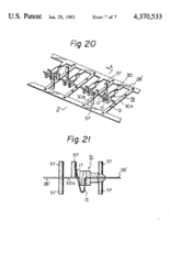
- FIG 20 is a perspective view showing another of the manufacturing process of the drive according to the present invention of the process.
- FIG 21 is a view showing the section taken along line A A in FIG 20.
Cited patents
- US 1502785, "Pushbutton switch", issued Jul 29, 1924
- US 2601545, "Push on-push off single button", issued Jun 24, 1952
- US 3909564, "Keyboard assembly with foldable", issued 1975
- US 4029916, "Multi-contact push-button switch and plural embodiment for keyboard switch assembly", issued Jun 14, 1977, assigned to Northern Electric Company Limited
- US 4129763, "Push button switch assembly", issued Dec 12, 1978, assigned to Alps Electric Co., Ltd.
- US 4177367, "Push button switch", issued Dec 4, 1979, assigned to Amf Incorporated
- US 4207448, "Pushbutton switch", issued Jun 10, 1980, assigned to Oki Electric Industry Co., Ltd.
Referenced by
- US 4445164, "Lighted key module assembly", issued Apr 24, 1984, assigned to Cherry Electrical Products Corporation
- US 4453061, "Capacitance type switch having dust-free interior", issued Jun 5, 1984
- US 4492838, "Key switch having an actuator integral with the return spring", issued Jan 8, 1985, assigned to AMP Incorporated
- US 4590342, "Panel mounted switching device", issued May 20, 1986, assigned to Firma Georg Schlegel
- US 4691086, "Pushbutton electrical switch having a flairing contactor loosely rotatable on a spring-biased eyelet", issued Sep 1, 1987, assigned to Indak Manufacturing Corp.
- US 4713507, "Key operated switch for keyboard", issued Dec 15, 1987
- US 6781077, "Keyswitch and actuator structure", issued Aug 24, 2004, assigned to Think Outside, Inc.
- US 7138594, "Push switch", issued Nov 21, 2006, assigned to Hon Hai Precision Ind. Co., Ltd
- US 7745748, "Switch having a complementary diode unit", issued Jun 29, 2010, assigned to MEC A/S
- US D559194, "Electrical switch", issued Jan 8, 2008, assigned to MEC A/S
- US D581363, "Button assembly", issued Nov 25, 2008, assigned to Caroma Industries Limited
- US D581364, "Button assembly", issued Nov 25, 2008, assigned to Caroma Industries Limited
- US D581368, "Button assembly", issued Nov 25, 2008, assigned to Caroma Industries Limited
- US D588068, "Button assembly", issued Mar 10, 2009, assigned to Caroma Industries Limited
- US D588069, "Button assembly", issued Mar 10, 2009, assigned to Caroma Industries Limited
Images
References
- ↑ 1.0 1.1 1.2 * US patent 4370533, Seisuke Kamei; Hideo Nabetani; Ryohei Kinoshita, "Keyboard switch and process for production thereof", issued 25 January 1983, assigned to Fujitsu Limited
