Kroy 360
| This article requires additional photographic illustration |
 | |
| Branding | Kroy |
|---|---|
| Manufacturer | Kroy |
| Layouts | Domain specific |
| Keyswitches | Hi-Tek Series 725 |
| Keycaps | Dye-sublimated PBT |
| Interface | 8P8C Modular Jack |
| Years of production | 1987 |
| Discontinued | Yes |
Contents
Description
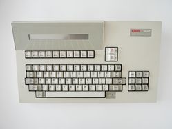
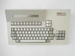
The Kroy 360 keyboard is part of the Kroy 360 Lettering System, an industrial tape label printing system from the late 80's. The system has two components, a keyboard unit and a printer. The keyboard has a graphical LCD to allow label text to be composed and edited.
Hi-Tek keyboard
The keyboard uses a custom 725 series NMB/Hi-Tek PCB using the standard Misubishi M5L8408 microcontroller. A 0.060" steel plate supports the switches and mounts the keyboard to the lower half of the case. The upper and lower case halves are molded from very thick ABS plastic.
Layout
The Kroy 360 uses a standard QWERTY layout for the alphas, but it uses non standard modifiers. On the right hand side of the keyboard is 3x3 orthogonal block of custom function keys supporting management of label projects and controls of the printer. The alphas are side-printed with alternate symbols in green. A 9u spacebar is used.
Switches
The Kroy 360 uses NMB/Hi-Tek "Space Invaders" switches.
Location Color Type Eye(s) Space bar (9u) White Linear Two All other keys white Linear Two
Gallery
Interfacing
The Kroy 360 keyboard unit is connected to the the printer unit via flat coiled cable with 8P8C module jacks. This connection is used to provide power from the printer to the keyboard and transfer label print information from the keyboard to the printer. This connection can not be used to determine what keys have been pressed. In order to interface the keyboard on a per key basis, the internal header on the keyboard pcb must be used.
The keyboard unit can be used in a standalone configuration by supplying 5V via the DC barrel jack on the rear panel. The size of the barrel is 6.3 mm OD x 2.5 mm ID but the more standard 5.5 mm OD x 2.5 mm ID size will work. Note: The polarity of the power jack is center negative while most commonly available wall-wart style power supplies are center positive.
The keyboard unit contains a keyboard assembly and a main board. The two are connected with a 20 pin ribbon cable using female 2x10 connectors with 2.54mm pitch. The pinout of this connection is the same on both the mainboard and keyboard.
Pinout
Pin Function Pin Function 1 DR - Data Ready 2 CT - Continue (from host) 3 KS - Key State (Down = High) 4 Edit Mode LED (Active Low) 5 D6 6 Type Specs LED (Active Low) 7 D5 8 Caps Lock LED (Active Low) 9 D4 10 GND 11 D3 12 GND 13 D2 14 GND 15 D1 16 GND 17 D0 18 Unused 19 5V 20 5V
Timing Diagram
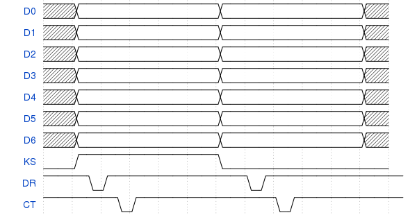
Key scan codes are sent as a 7 bit, parallel value on data lines D0 through D6.
When a key is pressed, Key State(KS) will transition from low to high and Data Ready(DR) will pulse low. The host issues a Continue(CT) with a low pulse to acknowledges data reception. Note: if the Continue pulse is sent too soon after the Data Ready pulse is received or the pulse is too short, the keyboard may miss it. A delay of 100us and a pulse width of 20us has been used succesfully.
When a key is released, Key State will transition from high to low and DR/CT handshake will repeat. Data Ready can be used to latch/read data from data lines D0 through D6.
Note: Key State (Pin 3) tracks the last key event and is common to all keys.
Scan codes
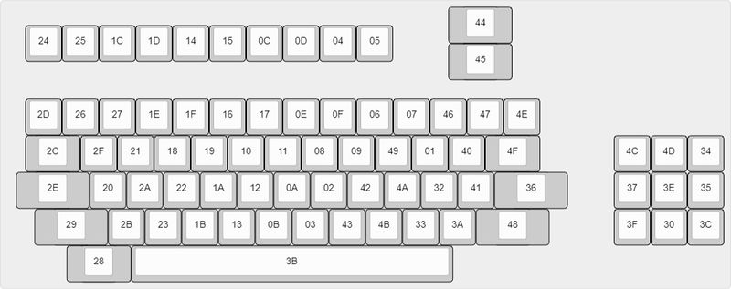
The scan codes generated by the keyboard via the 20 pin header are shown in the diagram below:
