Phantom instruction guide
Contents
Parts:
- If you are new to soldering, here is something that might help, available in many different languages: http://mightyohm.com/blog/2011/04/soldering-is-easy-comic-book/
Hardware
- Cherry plate-mounted switches
- PHANSI125: 87 switches
- PHANSI150: 86 switches
- PHISO125: 88 switches
- PHISO150: 87 switches
- PH7BIT: 101 switches
- 1 mounting plate
- 1.5u modifier front row layout: Ctrl, Win, Alt, 7u spacebar, Alt, Menu, Ctrl
- 1.25u modifier front row layout: Ctrl, Win, Alt, 6.25u spacebar, Alt, Win, Menu, Ctrl
- 4 2u wide stabilizers (Cherry or Costar)
- 1 spacebar stabilizer
- 6.25u or 7u
Electronics
- Diodes
- Mouser: http://www.mouser.com/Search/ProductDetail.aspx?R=1N4148TRvirtualkey61370000virtualkey78-1N4148
- Digikey: http://www.digikey.com/product-detail/en/1N4148/1N4148FS-ND/458603
- Online Components: http://www.onlinecomponents.com/synsemi-1n4148tr.html?p=12650385
- 1 diode for every switch
- 2 LEDs
- 2 LED mount supports
- 2 resistors, if LEDs are not 5V (e.g. 3.5V)
- resistor value:
- Pick any T1 package LED (3mm round). Forward voltage "V" and forward current "I"
- Pick any with resistance R=(5-V)/I
- 1 PCB
- 1 Teensy 2.0
- 2 pin sets to connect Teensy to PCB
Tools needed
- Soldering iron
- Solder
- Wire cutter to cut off component pins
- De-soldering iron, if rework is necessary
- Multimeter, though not required, could be useful to test for circuit continuity
Time
Below is an estimate on how much time it would take for each step. Total time will be around 4 to 5 hours if you are doing it the first time and everything works as expected. Of course it would take less time if you are good at this, longer if you don't do soldering work all the time or if you run into problems.
- Filing the stabilizers' corners on the plate and testing stabilizers fitting: 30 minutes to 60 minutes
- Inserting diodes: 30 minutes
- Soldering diodes: 30 minutes
- Testing diodes connectivity with multimeter: 15 minutes
- Preparing Teensy legs: 10 minutes to 20 minutes
- Soldering Teensy onto PCB: 10 minutes
- Upload Teensy firmware from computer: 15 minutes
- Test Teensy functionality by shorting switch contacts on PCB: 10 minutes
- Soldering LEDs and resistors: 10 minutes
- Inserting Cherry switches onto mounting plate: 10 minutes (note a few switches' orientation are different than others)
- Aligning and coupling switches on plate with PCB: 10 minutes (note some switches' legs could be bend and must be straightened first)
- Soldering all switches: 30 to 45 minutes
- The rest of the work: install completed Phantom into keyboard case, install keycaps: 30 minutes
Step-by-step instruction:
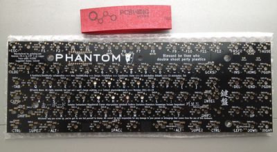
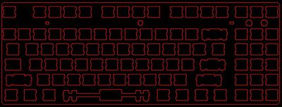
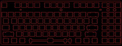
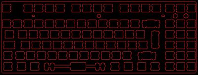
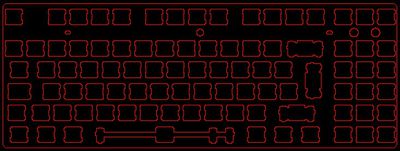
- Plan your layout. Phantom has 5 different plate options. With each plate, you can have 5 additional switches between your 6-pack keys and arrow keys.
- Because this plate design supports both Cherry and Costar stabilizers, there is a notch to fit Costar stabilizers where Cherry stabilizers' clip would hook to. Therefore, Cherry stabilizers are not fully secured. It is OK in general because the Cherry stabilizers should be very tight fit. On the occasions where Cherry stabilizers come loose when you pull a wide key out, just stick it back on to the plate.
- For Costar stabilizers should all fit well.
- [important!] For Cherry stabilizers, install stabilizers first before installing switches.
- For Costar stabilizers, you can install them in any order, switch first or stabilizer first.
- If you need to remove a Cherry plate-mount stabilizer, you will need to de-solder the switch for that stabilizer.
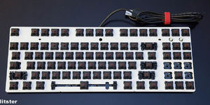
- IMPORTANT, switches for number 4 and 5 are rotated 180 degrees. Make sure they are inserted so on the mounting plate, or you will not be able to put the PCB and plate together to begin solder. If you use 7BIT layout, the key next to the dinky left Shift is also upside down. There is also an extra switch placement between Enter and \ that is rotated 90 degrees. Pay attention to that if you are using that switch location. Pro tip from bpiphany: I find that it is a good idea to mount only a few switches at strategic locations just to hold the plate in position above the PCB before putting in the rest. It is tricky to get all the little switch legs to find their holes otherwise. A slight bend and they easily ends up flattened to the switch bottom instead of in their holes. The ISO <> next to left shift is also mounted upside down, and the ISO enter is rotated 90 degrees (this is due to Costar stabilizer compatibility).
- IMPORTANT, Now is a good time to insert the wide keycaps, and test out the stabilizers, make sure they are not rubbing anything and are smooth. Do this now, or it would be a lot harder to fix after all switches are soldered.
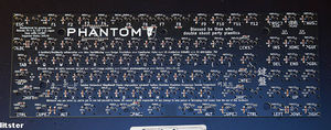
- Onto the PCB. Now that you know the layout you want and where all your switches are located, insert diodes for the switch locations you want.
- It is *very* important that all diodes are soldered in the same direction, or your keyboard's matrix would be broken. There is a black band on every diode. Orient the diode so that the black band on the diode is closer to the square soldering pad on the PCB. Most diode soldering pads have the square pads below the round pads. VERY IMPORTANT, for some switch locations, the square soldering pad is above the round pads. Pay attention!
- Once diodes are in, double check that all black bands on diodes are on the square pad end.
- Solder all diodes. If you didn't trim legs off of the diodes, trim them now. And careful not to cut anything else off or cut too close to the solder joints.
- Pro tip from bpiphany: I usually insert all diodes first, bending their legs on the back for them to stay in place. Sometimes I bend them back before soldering, other times I don't. Cutting legs after soldering might induce micro fractures in the solder joint (so I've read at least) but I've never bothered to cut before soldering and it have worked out fine this far (might be more important with really high frequency signals).
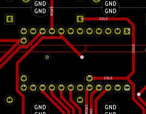
- Optional, but much preferred:Use a multimeter set to diode test or resistivity measuring. Pick the Teensy pad for each column and measure between that and the left pad of each switch in that column. They should all be connected in the same direction. Use the Teensy diagram on the right to guide you. Click on it to see a larger version. Note the pins are marked COL and ROW numbers, corresponding to columns and rows of switches.
- If everything is connected correctly, your keyboard matrix is complete. Welcome to 6KRO over USB. This PCB design has the potential of NKRO over USB with the right firmware. Keep an eye on the Phantom thread for new firmware development.
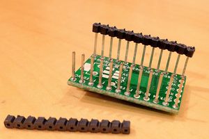
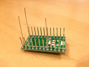
- Next, solder Teensy onto PCB. If your Teensy 2.0 has no legs, solder legs on. If you have legs and there are spacers on the legs, gently slide the spacers off the legs. Careful not to bend the legs or damage the Teensy circuit board. Make sure you also install legs to pin 13, 17, and 30.
- Pro tip: the legs you trimmed off of your diodes are great for Teensy legs.
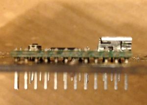
- Insert Teensy with pins on to PCB. Push Teensy as far in as possible without forcing it, without bending the pins, and make sure Teensy circuit board is not touching Phantom PCB. While the legs are sticking though the Phantom PCB, cut the pins flush to the Phantom PCB. This must be done in this way so the pins don't interfere with switches at these locations: F3, F4, 4, 5.
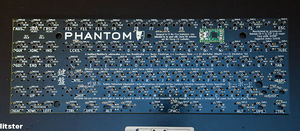
- Once the Teensy pins are cut flush to the Phantom PCB, solder the Teensy on to the PCB. Make sure the solder is not sticking out of the PCB when cooled. The solder joints must be flat. FLAT!
- With Teensy soldered, the circuit is not fully complete, but functional. Follow the firmware flashing instruction to upload the appropriate version of the firmware onto Teensy. (TODO: add link to Teensy firmware flash instruction)
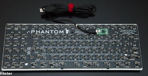
- with Firmware installed, your computer should recognize your Phantom keyboard when you plug the keyboard into a USB port on your computer. use something conductive (e.g. a loose legs from diodes, or a Cherry switch) to short a switch location. You should see that key is sent to the computer, and should show up on screen if a text edit box has the input focus. Try a few different switch locations. If it works as expected, you are close to half way done. If not, go back to check your soldering, and make sure firmware is installed correctly on to Teensy.
- a note, for if you test-short using a piece of wire rather than a loose-fit Cherry switch twisted to make pin contact: mechanical bouncing is normal and this is evidenced by ghost inputs should you repeatedly short it by tapping the contacts rather than simulating a single, held keypress. An actual switch is designed to minimize chattering so that the keyboard's debouncing still works as intended.
- Next is solder LEDs on. Two 3mm T1 LEDs are needed. They can be at the location above the 6-pack keys (Filco style), or they can be on the Scroll Lock switch and the Caps Lock switch (Leopold style). If LEDs are 5V (usually in red or green), you will need to connect the Resistor solder pads with just a wire. If LEDs are lower than 5V, for example, the white LEDs on Phantom prototype that Litster built, which is a 2.5V variant, you need a 75ohm resistor for each LED. Solder the resistors and LEDs. LEDs must be oriented correctly for it to function. You can test to make sure you have the correct orientation. After you solder in the wires (for 5V) or the resistors (for non-5V), plug the keyboard into your computer's USB port. Insert a LED onto the PCB, angle it a little so the LED pins are touching the soldering pads. If the orientation is correct, the LED should light up. Note the orientation. Solder the LEDs. Remember, in order to light up the LEDs, you need to press Caps Lock or Scroll Lock. You can do this by short these switch locations on the Phantom PCB, or if you already have another keyboard plugged in, toggling Caps Lock or Scroll Lock on that other keyboard will also toggle your Phantom keyboard.
- Pro tip from bpiphany: both voltage and current rating matters for the required resistor. In ubuntu the scroll lock LED is deactivated by default. And I think each keyboard's caps lock LED is activated separately... The anode of LEDs is usually a little longer, it is also usually possible to look inside the LED to identify the anode (the internal metal parts have different sizes). The anode should be connected to the round hole of the LED footprints.
- If the LEDs are too bright, you can adjust the brightness through the Teensy firmware. In phantom.c, there is a line at the end of the file to set OCR1B and OCR1C to a desired value. try values between 0 to 255 until you are happy. Yes, you could change resistor to different resistance value for different brightness. But flashing a new firmware only takes a few seconds. Whereas changing resistors would take a few hours if you need to desolder all the switches to get to the resistors in between the mounting plate and the PCB.
- You are more than half way through. Turn over the mounting plate, Check that all pins are pointing straight up, and not one is bended. with switch contacts pointing up, line up and couple the Phantom PCB onto all the switches. Check that all switch contacts are sticking through the PCB. If for some reason you can't do this, remove the PCB, check that no switch contacts are bent, and check that all switches are in correct orientation. Check that F3, F4, 4, and 5 are sitting flush to the PCB.
- After the PCB is seated, hold the PCB/Plate "sandwich" and flip it over. While facing the switches, push each switch into the plate again to make sure they are still flush with the plate. Some switches may have come back out a bit when you mated the PCB to the switches previously. After this check, flip it back over, and solder all the switches.
- Once all switches are soldered, turn the keyboard over. You keyboard should be fully functional, minus keycaps and a case. Test it out.
- If the keyboard is fully functional, you can now install it into a case.
- Congratulations! You have successfully built your own Phantom Custom Keyboard!
- If you need to hand make a Costar stabiliser bar below is a link to a video that shows you how. You need
- a Du-Bro E/Z Bender (0-90 degrees and Z bend)
- 3/64 inch music wire. Can be found at hobby shops in the USA. I found the ones I use at Hobby Town USA. It is called K&S Precision Metals Stock # 502 0.047 Music Wire (1.19mm).
- http://www.youtube.com/watch?v=zry3CHNKgT8
- If your Costar stabilizers feel a little sticky, here is what you can do:
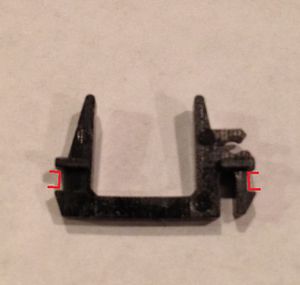
- In the first Costar star stabilizer picture on the right (scroll down a bit to see) the red areas need to be fully seated onto the plate. alaricljs's suggestion: Use a micro straight blade screw driver and gently press the black plastic piece toward the plate edge so that it engages properly. You may or may not hear a click as it seats itself. The tolerance is very tight.
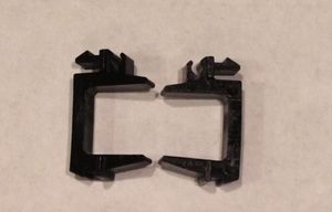
- Also, the stabilizer clips are made of plastic, so the width can vary. You can see the difference between these two in the picture on the right (scroll down a bit). Besides making sure the clips are seated perfectly, you can also gently bend the clip with your figures to make the gap wider. After this was done to a few Costar stabilizer clips, the wide, stabilized keys should not stick any more.
- If, and only if, the two techniques don't fix your sticky Costar stabilizers, the last resort is to file down slightly the areas marked as red in the first Costar stabilizer clip picture. Use a thin filer that fits in there and file just a little. after filing both sides down a little bit, it should fit very well on to the plate.
Flashing the firmware
- Follow PJRC's getting started guide to install the Teensy bootloader on your system, and learn the basics on using your Teensy.
- The firmware code and pre-compiled firmwares for different layouts is available from Bathroom Epiphanies' AVR-Keyboard github page.
- Bathroom Epiphanies know very little of either hardware, c-programming or github, but the creature is alive and working. The firmware is all open source - please feel free to contribute with your best to improve on the code.
- Also take a look at Hasu's firmware tmk_keyboard. It is more advanced and fancier.
- For an easier firmware option, there is also Easy AVR USB
See also
Phantom Group Buy to order all parts you need to build your Phantom keyboard.
Additional Resource
firmware thread on Geekhack: http://geekhack.org/index.php?topic=26742.0
Schematic http://deskthority.net/wiki/File:Phantom_schematic.pdf
Firmware source code: New, more general, better organized firmware source code by bpiphany: https://github.com/BathroomEpiphanies/AVR-Keyboard
Firmware with more features: https://github.com/Tranquilite0/Teensy-Keyboard
Best would be to combine to have only one source.
Firmware for Dox with layers, mousekeys and NKRO, but not yet compatible with Phantom: https://github.com/doxkb/tmk_keyboard
