Beamspring USB controller

xwhatsit

07 Jul 2013, 01:11

mr_a500 wrote:This is awesome! Every day I've been staring at my beamspring keyboard, waiting for the day I can actually use it. Now there's real hope!

I'm a bit worried about the way the connector is mounted. On the 3278, the spot where the edge connector is just happens to be the shallowest point on the case - only 4 cm from the bottom of the case to the cover. It looks roughly 2.5 cm from the bottom of the case to the top of the connector, so if that PCB overhang is much more than 1 cm, it might not fit. Isn't there an edge connector that mounts sideways? (like the original board)
Yeah that's my worry about the connector. There's a guy on GH with a 3278 and a 5251. He's building one---if it fits his 3278 then that's great, otherwise it will go on his 5251.

The particular connector spacing (3.96mm) isn't terribly common these days and there's really only that one connector I could find. In the worst case a simple right-angle adapter could be made up from another strip of PCB and some right-angle header pins (although the corresponding holes would need to be shrunk as header pins aren't normally 2mm diameter).

Thanks for the dimensions. Depending on how I interpret them it sounds like it may work. Total board height is 22.2mm. From the top of the keyboard PCB itself to the top of the controller board it will be 16.1mm (assuming 1.6mm PCB). The edge connector is 16mm deep, and won't plug fully onto the keyboard PCB, so it will stick maybe 20mm or so into the back of the case.
beamspring-pcb.png
beamspring-pcb.png (149.82 KiB) Viewed 7069 times
webwit wrote:Hmm, would it work with this 5251 66-key variant?
Almost certainly; you'd just program a different keymap into it.

xwhatsit

12 Jul 2013, 12:10

OK I've run out of PCBs and I'm getting low on the edge connectors too.

To meet some orders I'm about to order some more PCBs and possibly edge connectors, both of which have reasonable shipping times to NZ.

Before I put an order in for these bits, let me know if you are wanting to get either `option 2' or `option 3' through me, as it will save you a fair bit of time.

Cheers.

mr_a500

12 Jul 2013, 13:46

I'll go for an "option 3" - assuming it'll work (and fit) in a 3278. I want to do a custom layout, but I'll need you to program it because my main computer died and I only have MorphOS at the moment. I assume I can just edit a keymap file and send it to you?

xwhatsit

13 Jul 2013, 12:24

mr_a500 wrote:I'll go for an "option 3" - assuming it'll work (and fit) in a 3278. I want to do a custom layout, but I'll need you to program it because my main computer died and I only have MorphOS at the moment. I assume I can just edit a keymap file and send it to you?
Whoah Amiga OS. Cool.

Yes any keymap is possible and I can program whatever you like on it beforehand, but the only problem is I don't know the actual matrix layout of a 3278 itself (like what row/column is Return for example). You could figure that out by completely dismantling the whole board and looking at the matrix PCB directly but it's a bit of a pain (although not as bad as a Model F for instance).

It's a shame there's no libusb port for MorphOS. It may just be easier to use a PPC Linux liveboot CD or borrow somebody's Windows laptop to set the thing up.

I still don't know 100% if it will fit in a 3278. I've found some new connectors, which have proper 1mm PCB pins on them instead of 2mm lugs, which will allow me to slim down the board a couple of mm more, and make it easier to make a right-angle adapter if necessary.

If anybody with a 3278 could help me get absolute dimensions (maybe cut something out of cardboard...?) as in the post above then that would be really cool.

User avatar
Peter

13 Jul 2013, 15:49

I'll disassemble mine and post the dimensions when I'm back later this afternoon ..

User avatar
Peter

13 Jul 2013, 19:47

Hm.... I'm not sure if it will fit 'at an angle' :
IMG_1885.JPG
IMG_1885.JPG (541.97 KiB) Viewed 6966 times
IMG_1887.JPG
IMG_1887.JPG (535.98 KiB) Viewed 6966 times
IMG_1889.JPG
IMG_1889.JPG (523.19 KiB) Viewed 6966 times
I'll make a model tomorrow to check if there is clearance enough ..

xwhatsit

14 Jul 2013, 04:36

Thanks Peter, those photos are handy. It'll definitely fit rotated at 90°, but that would need a right-angle edge connector (as IBM initially used) but I cannot find one anywhere. It'd need an adapter board with some right-angle pin headers, which is a pain as it's more expensive (for another (smaller) PCB, and the hard-to-source (but not impossible) 3.96mm right-angle pin headers).

I'm more worried if it'll stand upright (as I mount it in my 5251 and 3727, as you can see in the photos on the first page). It's a skinny board but maybe not skinny enough.

The new batch of PCBs I just ordered is modified for a 1mm-diameter-pin edge connector (which I've been able to find, yay: http://www.ebay.com.au/itm/140887820225), so in theory if somebody had a 3278 and didn't mind desoldering the original connector off the original controller you could do that I think. I wanted to avoid doing that as desoldering is no fun and you're having to modify something I'd consider original and historic.

User avatar
bhtooefr

14 Jul 2013, 13:05

The other thing is, it looks like there's clearance to mount it upside down?

User avatar
Peter

14 Jul 2013, 13:58

bhtooefr wrote:The other thing is, it looks like there's clearance to mount it upside down?
No, there is only about 0.9mm from the plate to the bottom of the PCB,
but you could make a cut-out in the plate I guess, probably 'better' than de-soldering the old connector
in regards to preserving this old relic-board ..

My modeling showed that there isn't enough clearance, but it's very close and the model was just
an approximation, not exact, also it didn't take into account that the connector moves the board 20 mm backwards,
so maybe it does fit after all .. Any news on how it worked for that guy on GH ??

xwhatsit

16 Jul 2013, 10:25

Peter wrote: No, there is only about 0.9mm from the plate to the bottom of the PCB,
but you could make a cut-out in the plate I guess, probably 'better' than de-soldering the old connector
in regards to preserving this old relic-board ..

My modeling showed that there isn't enough clearance, but it's very close and the model was just
an approximation, not exact, also it didn't take into account that the connector moves the board 20 mm backwards,
so maybe it does fit after all .. Any news on how it worked for that guy on GH ??
No word from GH guy, I don't know if he's built it yet.

Ahhh that sucks. I keep scratching my head about a horizontal mount solution. No luck in finding a right-angle connector. Why IBM used 3.96mm pitch... it's very unusual (at least in this day and age, maybe it was very common back in the 70s?).

The only solution I can still see is an adapter board, using something like http://nz.element14.com/molex/26-48-124 ... dp/9732217 to mate to the main board. It just adds about 50% to the cost of the parts, that's all (the PCB still ends up having a large surface area and the pin headers are reasonably pricey because of the unusual size).

If you think it's really a no-go then I'll design an adapter board and figure out pricing for that.

User avatar
kps

16 Jul 2013, 16:08

xwhatsit wrote: Ahhh that sucks. I keep scratching my head about a horizontal mount solution. No luck in finding a right-angle connector.
Forgive me if this has already been considered (I don't have this type of keyboard) but what about manually bending the connector pins toward each other (perhaps using the lug version) and wedging the PCB in between?

xwhatsit

17 Jul 2013, 00:52

kps wrote:
xwhatsit wrote: Ahhh that sucks. I keep scratching my head about a horizontal mount solution. No luck in finding a right-angle connector.
Forgive me if this has already been considered (I don't have this type of keyboard) but what about manually bending the connector pins toward each other (perhaps using the lug version) and wedging the PCB in between?
Hmmmm...

Pretty damned rough, but might work! Designing the PCB with some nice big flat pads to bond to would make things easier.

I have the solder lug version with me now. The pins bend over pretty easily, there is some clearance but with enough solder it would work (and I think it would be robust). It wouldn't look particularly pretty though, mountains of solder!

When I get the pin version I'll check it out. The pins are round, so there will be less clearance in theory so that's great. However they still might need bending and that wouldn't work so well and there'd be less surface area.

User avatar
Compgeke

17 Jul 2013, 10:49

I have the original "Maintenance Library" from the 3278, and after a 2 second search I found these two pages that might be of help with the 3278, although probably not. I'll do a more through search whenever I get up...it's too late to bother reading.

And sorry for the jpeg noise, I happen to own a HP Officejet with a Potato powered scanner.

Image

User avatar
bhtooefr

18 Jul 2013, 02:26

Just got my controller from xwhatsit!

Interestingly, it'll randomly go hypersensitive on a random key, and then anything that even BRUSHES against that key actuates it, until the keyboard is unplugged and plugged back in. Suggestions? I could lift the assembly out and clean the PCB on both sides with isopropyl just to be safe... maybe clean the controller, too.

Edit: It was the PCB. The rubber layer was disintegrating, and gunk from it was on the PCB. Cleaned that off, seems to be working properly.

Also, I really need to figure out how to get these tools built on OS X (or just build a Linux VM - what distro are you using, xwhatsit?). Seems OS X comes with gcc 4.2, and this doesn't work with the diag tool.

User avatar
bhtooefr

19 Jul 2013, 01:05

For what it's worth, setting scan codes appears to do nothing at this point, on FreeBSD 9.1, built using gcc 4.6. Everything else seems to work, so...

Edit: I should say, the diag program is reporting that it set it. But, reading the matrix back, it's not showing as set, even after saving, unplugging, replugging, loading from EEPROM.

mr_a500

19 Jul 2013, 13:42

bhtooefr wrote: Edit: It was the PCB. The rubber layer was disintegrating, and gunk from it was on the PCB. Cleaned that off, seems to be working properly.
Whew. That's good news. I was worried that the controller was unstable.

User avatar
bhtooefr

19 Jul 2013, 14:45

Well, even if it was the controller, a failure of that nature would be a software failure most likely, in the calibration.

xwhatsit

20 Jul 2013, 05:52

Hey cool it arrived! You had me worried for a sec as I was reading about the random key but glad to see you sorted it out.

I've started work the past few days in my spare time on a graphical version of the util, using Qt. However it uses the same basic underpinnings as the command-line tool so it wouldn't help your problem.

I've just looked at the command-line tool's code and think I've made a cock-up—I think i swapped `cols' and `rows'—so maybe this is the problem. Try swapping it around, so instead of typing ./beamspringusb_diag_util -c 22x3=63, try ./beamspringusb_diag_util -c 3x22=63. The rows/cols are expressed in decimal, but the actual scancode is in hex, as that's what the USB HID scancodes are listed as in most places (you can prefix with 0x or not, it doesn't matter).

Certainly you should see an immediate result when running -x to read the matrix back, you don't need to write to EEPROM or anything.


Here's all you need to change to sort the cols/rows thing for -c:

Code: Select all

 @@ -373,7 +373,7 @@ int main (int argc, char **argv)
                  cerr << "setting scancode at column " << (unsigned int)col <<
                          " and row " << (unsigned int)row << " to 0x" <<
                          hex << (unsigned int)scancode << endl;
 -                sendCmd(dev, dcSetScanCode, row, col, scancode);
 +                sendCmd(dev, dcSetScanCode, col, row, scancode);
And the script I used to set the initial scancodes on your board (after fixing that swap):

Code: Select all

 #!/bin/bash

 ./beamspringusb_diag_util -c 0x0=0x2
 ./beamspringusb_diag_util -c 0x1=0x2
 ./beamspringusb_diag_util -c 0x2=0x2
 ./beamspringusb_diag_util -c 0x3=0x2
 ./beamspringusb_diag_util -c 10x0=22
 ./beamspringusb_diag_util -c 10x1=17
 ./beamspringusb_diag_util -c 10x2=0a
 ./beamspringusb_diag_util -c 10x3=5
 ./beamspringusb_diag_util -c 11x0=23
 ./beamspringusb_diag_util -c 11x1=1c
 ./beamspringusb_diag_util -c 11x2=b
 ./beamspringusb_diag_util -c 11x3=11
 ./beamspringusb_diag_util -c 12x0=24
 ./beamspringusb_diag_util -c 12x1=18
 ./beamspringusb_diag_util -c 12x2=d
 ./beamspringusb_diag_util -c 12x3=10
 ./beamspringusb_diag_util -c 13x0=25
 ./beamspringusb_diag_util -c 13x1=c
 ./beamspringusb_diag_util -c 13x2=e
 ./beamspringusb_diag_util -c 13x3=36
 ./beamspringusb_diag_util -c 14x0=26
 ./beamspringusb_diag_util -c 14x1=12
 ./beamspringusb_diag_util -c 14x2=f
 ./beamspringusb_diag_util -c 14x3=37
 ./beamspringusb_diag_util -c 15x0=27
 ./beamspringusb_diag_util -c 15x1=13
 ./beamspringusb_diag_util -c 15x2=33
 ./beamspringusb_diag_util -c 15x3=38
 ./beamspringusb_diag_util -c 16x0=2d
 ./beamspringusb_diag_util -c 16x1=2f
 ./beamspringusb_diag_util -c 16x2=34
 ./beamspringusb_diag_util -c 16x3=2c
 ./beamspringusb_diag_util -c 17x0=2e
 ./beamspringusb_diag_util -c 17x1=30
 ./beamspringusb_diag_util -c 17x2=31
 ./beamspringusb_diag_util -c 17x3=e5
 ./beamspringusb_diag_util -c 18x0=2a
 ./beamspringusb_diag_util -c 18x1=28
 ./beamspringusb_diag_util -c 18x2=53
 ./beamspringusb_diag_util -c 18x3=e4
 ./beamspringusb_diag_util -c 19x0=5f
 ./beamspringusb_diag_util -c 19x1=5c
 ./beamspringusb_diag_util -c 19x2=59
 ./beamspringusb_diag_util -c 19x3=2
 ./beamspringusb_diag_util -c 1x0=3a
 ./beamspringusb_diag_util -c 1x1=3c
 ./beamspringusb_diag_util -c 1x2=3e
 ./beamspringusb_diag_util -c 1x3=40
 ./beamspringusb_diag_util -c 20x0=54
 ./beamspringusb_diag_util -c 20x1=60
 ./beamspringusb_diag_util -c 20x2=5d
 ./beamspringusb_diag_util -c 20x3=5a
 ./beamspringusb_diag_util -c 21x0=61
 ./beamspringusb_diag_util -c 21x1=5e
 ./beamspringusb_diag_util -c 21x2=5b
 ./beamspringusb_diag_util -c 21x3=62
 ./beamspringusb_diag_util -c 22x0=55
 ./beamspringusb_diag_util -c 22x1=56
 ./beamspringusb_diag_util -c 22x2=57
 ./beamspringusb_diag_util -c 22x3=63
 ./beamspringusb_diag_util -c 2x0=3b
 ./beamspringusb_diag_util -c 2x1=3d
 ./beamspringusb_diag_util -c 2x2=3f
 ./beamspringusb_diag_util -c 2x3=41
 ./beamspringusb_diag_util -c 3x0=0x1
 ./beamspringusb_diag_util -c 3x1=42
 ./beamspringusb_diag_util -c 3x2=2
 ./beamspringusb_diag_util -c 3x3=43
 ./beamspringusb_diag_util -c 4x0=2
 ./beamspringusb_diag_util -c 4x1=e0
 ./beamspringusb_diag_util -c 4x2=e1
 ./beamspringusb_diag_util -c 4x3=2
 ./beamspringusb_diag_util -c 5x0=29
 ./beamspringusb_diag_util -c 5x1=2b
 ./beamspringusb_diag_util -c 5x2=35
 ./beamspringusb_diag_util -c 5x3=e2
 ./beamspringusb_diag_util -c 6x0=1e
 ./beamspringusb_diag_util -c 6x1=14
 ./beamspringusb_diag_util -c 6x2=4
 ./beamspringusb_diag_util -c 6x3=1d
 ./beamspringusb_diag_util -c 7x0=1f
 ./beamspringusb_diag_util -c 7x1=1a
 ./beamspringusb_diag_util -c 7x2=16
 ./beamspringusb_diag_util -c 7x3=1b
 ./beamspringusb_diag_util -c 8x0=20
 ./beamspringusb_diag_util -c 8x1=7
 ./beamspringusb_diag_util -c 8x1=8
 ./beamspringusb_diag_util -c 8x2=7
 ./beamspringusb_diag_util -c 8x3=6
 ./beamspringusb_diag_util -c 9x0=21
 ./beamspringusb_diag_util -c 9x1=15
 ./beamspringusb_diag_util -c 9x2=9
 ./beamspringusb_diag_util -c 9x3=19

User avatar
bhtooefr

20 Jul 2013, 14:09

The funny thing is, I actually mapped the layout in rowxcol in a text file, and then had to swap when actually running the diag util because it said colxrow. :P

Anyway, using rowxcol works fine. (Now to decide what I want to do with the numpad. This thing is mapped nearly perfectly for a Windows machine (it would need layer support to get PrtSc on Shift-2x18), but on my Mac, it needs a little bit more tweaking. See, Macs don't handle Num Lock. At all. So, basically, I get to simulate NumLock being off permanently, or figure out a software way to handle the numpad on OS X.)

User avatar
Muirium
µ

20 Jul 2013, 14:20

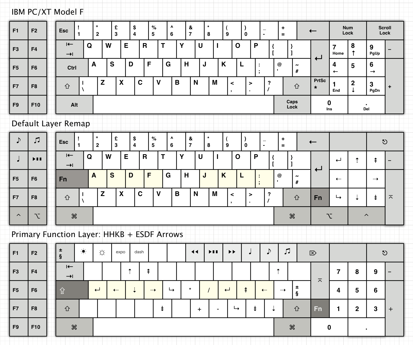
Here's how I mapped my XT Model F for Mac use, if it gives you any ideas:
Image
Num Lock is recognised by OS X, but used as some sort of "clear" instead of delete. Think it might clear a cell's contents in Numbers and Excel but not much else. Scroll Lock, meanwhile, is literally ignored. I made my Scroll Lock into a system power key (brings up the sleep / shut down dialog box), and Num Lock is now a macro for reverse colour mode (my favourite at night).

Layers are your answer if you want a typical numpad. Helps if you've got a latching modifier key, of course. Which I don't.

Parak

20 Jul 2013, 23:53

Just (finally?) did some pseudoaccurate measurements, and it seems that it just barely won't fit in a 3278, by about 2mm. There's ~10mm of clearance to the top of the case from the original edge connector, as determined by compressing some tinfoil on top of it. I think that it's not too big of a deal, as it's obviously possible to shim the case top to be higher with some washers or somesuch...

User avatar
Peter

21 Jul 2013, 00:26

I guess something like this could be made.. A lot of soldering and messy, but it would work ?
Image

User avatar
bhtooefr

21 Jul 2013, 02:33

Given that all of this works on capacitance, I wouldn't even think of using cabling to relocate the controller.

xwhatsit

21 Jul 2013, 04:53

@bhtooefr: Yes, no layer support. To implement that I'd first need to work out exactly what they're supposed to do :) (having never owned a HHK or used Soarer's converter, so I don't personally have a use for them—although once I try it out that may change :)). If `layers' is what I think it is it wouldn't be difficult at all to implement, somebody could easily roll their own into my open-source code if they wanted to.

Yep I agree re. using cabling, you want to keep those signal traces as short as possible, and not too close together for crosstalk etc.

@Parak: cool, thanks for that. I've just received my `PCB-mount' version of the connector. It's basically identical to the solder-lug version but the pins are skinnier, so that won't help for surface mounting. I still think surface-mounting is definitely possible, and the nice thing is that it would mean you could use either the PCB-mount or solder-lug connector on the same PCB. That's handy because I have 2 solder-lug connectors left but at least from OSH Park you have to order in multiples of 3 boards :P

I didn't think about shimming the case. It might look a bit ugly though—isn't the seam on the case visible on the sides halfway up, like the 5251/3727s?

I think some sort of jig or set of shims or something whiel soldering would be necessary to make surface-mounting the connector not look like arse. I'll have a play around tomorrow on my lunchbreak. If the pins are 3.96mm apart, let's say 3.8mm inside dimension taking into account pin/lug thickness, and the PCB is 1.6mm thick, that means 1.1mm either side to space out to keep it centered while soldering. I'm sure something can be found—if not, the nice thing about working at a rollformer manufacturer means there's plenty of 1.2mm steel coil sitting around :)

User avatar
Muirium
µ

21 Jul 2013, 13:59

Layers very likely are exactly what you think. Hold the chosen mod (which is hidden from the computer entirely) and subsequent keystrokes are remapped in a configurable way. Like the lower two diagrams I posted earlier.

Layer 0 is the default. Layer 1 is all most users might need. But Layers 2-8 or more are available in Soarer's converter and the related tmk_keyboard custom controller that I have a second Teensy set aside for. Various combinations of layer keys (all invisible from the host) can shift to different layers. A layer lock is the feature I'm looking forward to, where those of us without latching keys can simulate them.

Layers are a huge win for small layouts and they work well on old classics which predate current conventions, too.

mr_a500

21 Jul 2013, 16:59

xwhatsit wrote:I didn't think about shimming the case. It might look a bit ugly though—isn't the seam on the case visible on the sides halfway up, like the 5251/3727s?
I thought about shimming the case, but I assumed it would look too awkward. I just checked and if it's only 2mm, it won't look as bad as I thought. Even 5mm is tolerable. The keys sink in a bit and you can see some of the bottom of the case from the side, but I could still live with that. (...hell, I'd probably even go caseless if I could actually use this keyboard)

Damn, it's a shame they don't make a right angled version of that connector. I've searched. You can get it in 4 different colours, but you can't get it right angled.

mr_a500

21 Jul 2013, 18:49

xwhatsit wrote:
mr_a500 wrote:Yes any keymap is possible and I can program whatever you like on it beforehand, but the only problem is I don't know the actual matrix layout of a 3278 itself (like what row/column is Return for example). You could figure that out by completely dismantling the whole board and looking at the matrix PCB directly but it's a bit of a pain (although not as bad as a Model F for instance).
OK, I dismantled the 3278 keyboard to get a picture for the matrix*
3278board.jpg

*(...not to be confused with a picture of The Matrix - which looks like a bunch of green text ;) )

mr_a500

21 Jul 2013, 18:53

Peter wrote:
8619.jpg
Strange that the plastic surround on your switches is blue. On mine, it's black:
3278.jpg

mr_a500

21 Jul 2013, 19:48

Even though I was very careful disassembling my 3278, after reassembling I discovered that my Return key was not clicky. The damn fly plate had somehow detached. I had to completely disassemble again, remove the switch and reattach the spring. Luckily, Deskthority has convenient manual instructions for reattaching the fly plate, so it wasn't as horrifying as it could have been.

User avatar
kps

22 Jul 2013, 20:34

mr_a500 wrote:Even though I was very careful disassembling my 3278, after reassembling I discovered that my Return key was not clicky. The damn fly plate had somehow detached.
You're lucky. When I disassembled my Displaywriter keyboard, five beam springs broke. (They might have been broken already, and only come free of the heat stake when the fly plate was able to move further than normal.)

Post Reply

Return to “Workshop”