Murium, Findecanor, thank you for the useful info about sides!
Findecanor wrote: AFAIK, all of
Cherry's own keyboards with PCB-mounted MX-switches are single-sided but most of them are actually manufactured double-sided with the top-facing side as a single ESD/ground plane connected to the wire's shield. If there was a plate, the plate would be connected to shield instead.
I'm trying to create the new PCB for the old WYSE terminal keyboard, it's switches are plate mounted and the plate is connected with the PCB ground; I want to do exactly the same.
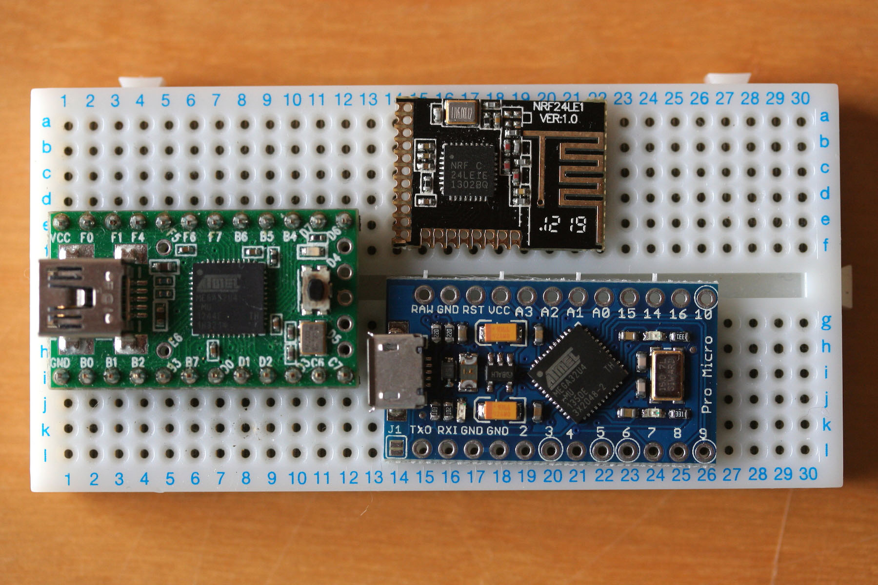
So far - so good. Please, help me to clear one more thing I'm stuck with. Teensy 2++ has 2 VCC legs and 3 GND legs. I connected each VCC leg with VCC component from library and each GND leg with power port. I've called them: "Component Ground - #PWR01", "Component Ground - #PWR02", "Component Ground - #PWR05", "Component VCC - #PWR03", "Component VCC - #PWR04".
But Electric Rules Check said:
Code: Select all
ErrType(3): Pin connected to some others pins but no pin to drive it
    @ (97,79 mm,69,85 mm): Pin 1 (power_in) of component #PWR04 is not driven (Net 42).
and highlighted one of GNDs (pin1) and one of VCCs (pin52) with the green arrows.
What am I doing wrong?
Thank you in advance for the tips!
 )
)
