Katy keyboard (or K80CS (Key80 Contoured Split))

kiltannen

20 May 2015, 06:12

infowolfe wrote: I'm very excited to see how the k80cs turns out.
<SNIP>
Anyway, keep up the good work... you've designed one of, if not THE most compelling "original" (not a modified ape of another open source design) keyboards in years. I dig the Maltron-ish key pitch/layout, the split halves, and the LCD for layer tracking/output is icing on the cake.
In case it's not obvious I would like to add my accolades to the work you have done here! Once I saw your design I just knew it would be what I wanted.
infowolfe wrote: it'd be really super awesome if by 1.0 it had a hub and at least 1 'child' usb header, for Yubikey/2FA hardware token.
I also think this would be a super awesome idea! Having a USB hub on the actual keyboard just makes so much sense!

I was personally planning to do something like have a Hub that I could mount inside the K80c which had one of it's ports inside the case and plug the Katy into that...

User avatar
vvp

21 May 2015, 01:33

I discussed jacobolous' thumb cluster quite a bit with him in his thread on geekhack. I think it is better for a flat keyboard. I think that for a contoured keyboard the maltron like thumb cluster is better. Here is the main idea of my reasoning (at least that is the way it works for me): With proper curving, the bottom row keys are easier to hit with fingers than with thumbs. That is true for all the columns except the pointing finger column where it does not really matter (it is as comfortable to hit it with pointing finger as with the thumb). When the curving is missing it is better to hit the bottom keys with thumb down to ring finger column (where it starts to be questionable again whether thumb or finger is better). So jacobolous reassigned some bottom row keys from finger to thumb and positioned them better for easy reachability by thumb. I think that is a very good idea for a flat keyboard. Not good idea for contoured keyboard.

I'm not really sure why the far thumb cluster column was completely removed in jacobolous design. I guess that is because of worse reachability by smaller hands. My hands are on the average or maybe even the bigger side. I do not have any problem to reach the two bottom keys of the far thumb cluster column both on kinesis and katy. It is true that the thumb cluster is about half a key more far away in horizontal plane on ergodox than on katy. And Katy's thumb cluster is higher (so nearer to the thumb root too). The difference probably makes the far thumb column barely usable or unusable on ergodox (especially for people with smaller hands).
On Katy, the worst reachable thumbcluster key is the top key of the far thumb cluster column (Alt on Kinesis layout). I'm hitting it on it's bottom half only (if I do not move wrist position). But works well enough. I have no regrets having it there and I want it there.

I do not know HaaTa's firmware nor his KLL. I may look at it later. If his firmware has an option to select a LUFA backend then it is easy to port to Katy.
I really like chrisandreae's firmware (which is used on Katy by default too). Especially on-the-fly Remap. I really like that when I want to try some keys on a different location then I can just change that quickly with few keystrokes and test the new layout. If I like it then I can continue using it. If not I can save it into config (again only few keystrokes, no special application needed) and return to the default. And later again return to the modified layout quickly. The config actually serves as store for multiple layouts. Its only problem to full unlimited multi layout feature is that: there is only 10 layouts there, they cannot have custom names assigned, and are invoked by specific keystrokes including numbers 0 - 9.
Chris' firmware comes with PC application which allows to assign USB HID code so that probably covers what KLL does ... though it would be good if it could export/import layouts to/from a text file.
And finally, Chris' firmware has a built in interpreter which allows me to write small timed macros etc. As far as I know, no other firmware has this. More thumb cluster keys and this were my primary reasons I started Katy (instead of just continuing using kinesis).
On the other side, Chris' firmware is only 6KRO. But I never needed anything more. I play games sometimes but one hand is dedicated to mouse, so 6KRO was always enough for me.

I'll check out #deskthority channel.

As for as the case availability. I wanted to target the most common (and the most cheap) 3d printer which is an FFF/FDM reprap. That also means a slow printer which requires a considerable clean up of the parts after they are printed and support material was required. Except the dual extrusion models which can print water soluble support material with one head - this makes the clean up easier. That limits how much cases one can build. Probably only up to ten till it starts to be really boring. The other option is to use SLS or SLA 3d printer. Katy is printable with them almost without any modification and there is almost no post-processing needed. There are also quicker compared to FFF/FDM. This would be a good option up to a hundred or few hundreds of pieces. I want to buy an SLS 3d Printer for other things beside Katy. If I can get a good one for "cheap" (up to 10 - 20 thousands). Then I can get some cases for community cheaper than shapeaways. For higher volume, the other options are vacuum forming or injection molding. I do not know much about these but I believe a case redesign is needed here. We probably never get there, so it is just empty speculation.

Yes, KKO prefers to have a USB hub built in too. And a track point. We leaved it out for the first versions.

User avatar
vvp

27 May 2015, 23:04

This is mostly for kiltannen and possibly others who want to look at it even in parts (instead of waiting for the complete drop). You can download the kicad project files here.
The files were crated with: kicad-bzr, version r5648-1; build date Sat 09 May 2015 02:16:01 PM CEST.
Reasonably recent git version of kicad should not have any problems to open the files.
Do not forget to read the readme.txt file in the ATxmega directory!!!

I intended to put it on github but it does not allow account sharing which would be convenient for me and kko. So git access will be sometimes later. I'll try to get the case STL files out as soon as possible ... probably in about 2-3 weeks. Yeah and the firmware (maybe even before the case STL files).

kiltannen

28 May 2015, 22:36

So - it looks like this might be the best switch drop since I started following the Katy project...
Massdrop Gateron Buy

Clearly they will be more than enough units to do a whole Katy Kbd.

What do you think?

User avatar
vvp

29 May 2015, 01:36

I have them too from this geekhack/deskthority group buy. It also achieved the cheapest price for this switch kind (0.16$).

There are links to some reviews from the group buy. I did not put them into any keyboard yet. They seem fine at first look. I'll know more when I built some keyboard from them. But I'm one of those who are not picky about switches. E.g. I would not ever consider lubing switches or replacing springs. The linked reviews will be from people who care much more about switch kinds.

The only bad thing I read about them is that they may not work well with thick PBT keycaps. Keycaps which have thicker stem than it is common. Such thick stem may get in contact with switch housing and may result in scratchy movement. The problem is not there with thin SignaturePlastics and OEM keycaps I have. It is also not there with my 3dPrinted keycap you can see in this thread somewhere earlier.

infowolfe

29 May 2015, 13:35

vvp wrote: This is mostly for kiltannen and possibly others who want to look at it even in parts (instead of waiting for the complete drop). You can download the kicad project files here.
The files were crated with: kicad-bzr, version r5648-1; build date Sat 09 May 2015 02:16:01 PM CEST.
Reasonably recent git version of kicad should not have any problems to open the files.
Do not forget to read the readme.txt file in the ATxmega directory!!!

I intended to put it on github but it does not allow account sharing which would be convenient for me and kko. So git access will be sometimes later. I'll try to get the case STL files out as soon as possible ... probably in about 2-3 weeks. Yeah and the firmware (maybe even before the case STL files).
Would it be possible to get an estimate from shapeways on the STL files before they're published? I'm curious to know ballpark what it'd cost from them.

User avatar
vvp

29 May 2015, 22:38

infowolfe wrote: Would it be possible to get an estimate from shapeways on the STL files before they're published? I'm curious to know ballpark what it'd cost from them.
Ok, I uploaded the right side of the case to shapeways and the prices are:
  • top part of the case (*) is 93.96$ (1.5 labor, 25.9 volume, 66.56 machine volume)
  • bottom part is 38.64$ (1.5 labor, 13.12 volume, 24.01 machine volume)
(*) For RepRap FFF/FDM pritners, the top part is divided into two separate pieces which are later glued together. On SLS printers, it is printable in one piece.

So the approximate price would be about 2 * (94 + 39) = 266$ for the cheapest option - the white plastic. This price probably does not include shipping and VAT (for EU customers). The price was only taken from the material selection page.

Just for fun I looked how much it would be with the cheapest metal option on the page. It was stainless steel (no clue why no aluminum option there). The cost would be about 1440$ but this is very approximate since model would need to be modified quite a bit to be probably mill-able (???) in stainless steel. It complained a lot about too thin walls. Currently, the minimal wall thickness in the model is 1.6 mm.

Even the plastic model price is not precise since the model would need few tweaks to be printable better on SLS printers. There are some features added specifically for RepRap FFF/FDM printers which should be removed. This would decrease price a little bit (probably only few cents). On the other side I'm not sure shapeways adds support pillars automatically. I guess they do since they did not complain about missing support. SLS 3dPrinters require thin support pillars from the bed to the parts of the model which would start to be printed in the powder without any connection to already printed plastic in the previous layer.

Anyway, it looks like it is possible to make models on shapeways public and receive a small fee for prints of the model. If so I can upload an SLS printer optimized model to shapeways and publish it. Or I can add it to the set of the models for FFF/FDM printers. People should express their interest if they want it. But first the RepRap versions since I need them myself to test the case (test that everything fits together).

Still the cheapest option is if you can find somebody locally with a RepRap with bed size of about 19x19 cm. Material: ABS. It is probably doable in PLA too, I did not try that. The material cost for whole case (all parts together) on a RepRap printer is about 8€. If you are willing to do all the post-processing yourself then I think people will be willing to do it, well if not for the material cost then possibly for about 50 - 100$. If their RepRap is not a piece of shit then it is just starting the printing and letting it run. There is no needed to babysit it. I'll post the RepRap print times when I'll print my case (in a week or two?). I believe everything together should be below 20 hours of RepRap machine time ... it depends a lot on maximum acceleration and maximum speed of the printer.

User avatar
vvp

31 May 2015, 11:56

Heads up for kiltannen (and maybe others who started to work on electronics ... if any).

It is probable there will be a new version of kicad files for the electronics. We realized that we should be able to limit the initial photo-transistor current in direct sun with the FET transistor which controls the photo-transistor power. To allow this photoSns and photoDrv lines must be swapped on the controller pins. This way we should be able to finely control photoDrv net with DAC and avoid the spike. It is still not known whether cleaner AVcc related stuff helps enough to be worth the trouble. The sensor data still need to be averaged anyway so the noise there does not matter much.

Anyway this concerns you only if you started to actually work on the electronics.

kiltannen

31 May 2015, 12:27

vvp wrote: Heads up for kiltannen
Thanks for the heads up. While I hadn't yet started work on the electronics - I HAD downloaded the files - and wouldn't have re-downloaded them without this warning!..

User avatar
vvp

31 May 2015, 16:09

Sure. I did not update the files on the web yet. I'll post when it is done. The only expected change is swap of photoDrv with photoSns.

User avatar
vvp

03 Jun 2015, 01:36

Errara: PCB stencil layer: Yellow and Green LED marking on stencil layer were swapped. The LED part numbers were correct. The schematic was correct too.

CrimsonFlame

04 Jun 2015, 19:58

Awesome project. I really like what you've done with this, and can't wait to try printing. If you need someone to prototype prints, let me know. I have a Lulzbot Taz4 (295x275mm bed) and can print ABS/PLA.
vvp wrote: I intended to put it on github but it does not allow account sharing which would be convenient for me and kko. So git access will be sometimes later. I'll try to get the case STL files out as soon as possible ... probably in about 2-3 weeks. Yeah and the firmware (maybe even before the case STL files).
Regarding Github, you can easily give another account holder write access to a repo (make them a collaborator under settings [0]). Another option (if you both want ownership) is to create an Organization under a Github account, and add kko to the "team". You can then add him to the org as an owner [1]. You then base all shared repos under that org, and you both will have write access. Just remember to take care with conflicts. It would be best to adopt a specific git pattern and make sure you both stick to it. My personal favorite scheme is to use pull requests to merge from personal repos for each person in the team.

I don't have a paid Github subscription, but I assume the controls should be identical on a private repo.

Source: Avid Github user/fanboy.
vvp wrote: On the other side I'm not sure shapeways adds support pillars automatically. I guess they do since they did not complain about missing support. SLS 3dPrinters require thin support pillars from the bed to the parts of the model which would start to be printed in the powder without any connection to already printed plastic in the previous layer.
You shouldn't need supports in SLS. An SLS machine fills the print chamber volume with powder, so it is self-supporting, and doesn't need your slicer/modeler to support for you [2]. The biggest concern with SLS is closed volumes. If your model has a closed volume, there will be no way for the unused powder to escape, and you *will* be billed for it. But from the looks of your model, that will not be a problem with this.

[0]: https://help.github.com/articles/adding ... epository/
[1]: https://help.github.com/categories/sett ... and-teams/
[2]: https://youtu.be/oy3cnQVtzD8?t=44s

User avatar
vvp

05 Jun 2015, 21:55

CrimsonFlame wrote: Awesome project. I really like what you've done with this, and can't wait to try printing. If you need someone to prototype prints, let me know. I have a Lulzbot Taz4 (295x275mm bed) and can print ABS/PLA.
Thanks, I have a printer here. I'll try to print the last version this weekend (or the next weekend if something more important would jump into my schedule). It will be available after I successfully print it. There is a small change compared to kko's case (which is the last case I printed). It should not cause any problem but there is about a hundred of features to be replayed in the CAD tool and something could go wrong there. Not probable but possible.
CrimsonFlame wrote: Regarding Github, you can easily give another account holder write access to a repo (make them a collaborator under settings [0]). Another option (if you both want ownership) is to create an Organization under a Github account, and add kko to the "team". You can then add him to the org as an owner [1]. You then base all shared repos under that org, and you both will have write access.
I did not know this. Thanks. I'll talk to kko.
CrimsonFlame wrote: You shouldn't need supports in SLS. An SLS machine fills the print chamber volume with powder, so it is self-supporting, and doesn't need your slicer/modeler to support for you [2]. The biggest concern with SLS is closed volumes. If your model has a closed volume, there will be no way for the unused powder to escape, and you *will* be billed for it. But from the looks of your model, that will not be a problem with this.
There is no closed volume in the model. Though the model has sometimes thicker walls than it is needed from the strength point of view. It is almost no issue for FFF/FDM printers since they can do sparse infill. So from the strength point of view it is often better to just increase volume and use sparse infill instead of adding strengthening ribs (as it is more suitable for SLS printers).

As for as support need with SLS printers. I was told it is not that simple. Look e.g. at the model on this picture:
coneInCan.png
coneInCan.png (8.52 KiB) Viewed 16685 times
It is an hollow cylinder without the bottom side and with a square cut out at its side. A cone is hanging from the top of the can. The tip of the cone is higher than the bottom of the cylinder.
The problem is that the tip of the cone would start to be printed as a small isle in the plastic powder without any connection to the other parts of the model or to the bottom (the bed). When the next layer of powder is deposited (I believe it happens at 0:35 of your video) then the carriage depositing the powder can move this unconnected tip of cone. This would result in a bad print. The problem is solved by adding a thin pillar from such isles (in our case the tip of the cone) to the bed or to the side of the model. The pillars will keep the isle in place. The result is that even SLS printers need some support. Of course, it is much less support compared to the FFF pritners. E.g. the model on the picture does need a support in the square cutout when printed using FFF but does not need it when an SLS printer is used.

Edit: Maybe some SLS printers can deposit the new powder layer without disturbing the previous one. Then they would not need any support at all.

User avatar
vvp

07 Jun 2015, 18:48

I talked about getting raw printouts from an FFF reprap printer. It should be possible to get these cheaply (definitely compared to shapeways). Here are some examples what the delivered parts would look like:
rawKeyPartTop.jpg
rawKeyPartTop.jpg (68.31 KiB) Viewed 16663 times
rawKeyPartBot.jpg
rawKeyPartBot.jpg (71.46 KiB) Viewed 16663 times
rawPalmPartBot.jpg
rawPalmPartBot.jpg (42.93 KiB) Viewed 16663 times
These were printed with ABS on a reprap (linear delta bot) which does not have a heat chamber. The print took 3h 37m for the keyPart and 1h 20m for the palm part. It was printed at 120 mm/s print moves, 240 mm/s non-printing moves, 7200 mm/s² X/Y/Z acceleration. This is kind of a middle of the print speed range for a delta printer. It is on a high end of the range for a cartesian printer. The delta pritner used a bowden extruder so you can see some strings there. A lot of cartesian printers do not use bowden extruders and should provide a cleaner result but in a longer time.
You can see the adhesion pads to prevent curving of the model during printing (needed for ABS when there is no heat chamber). You can sometimes see plastic strings which should not be there. And of course the support structure on the keywell part.

To finish the top part of the case one would need to do these things:
  • cut away the adhesion pads
  • pry away the support material
  • clean up (cut away) the strings (if any)
  • paint it with acetone
  • fix possible delamination or broken parts with acetone or ABS-glue
  • glue the two parts together with ABS-glue (there is a gluing template shape to make this easier)
  • optional - smooth it with sand paper
  • optional - paint with acetone or give it an acetone vapor bath
So now you can consider whether the chores are worth the cheaper price :D
If you do that without the last two optional steps (I did not bother) then it will look approximately as the pictures I posted earlier.
Even if it looks bad, the ABS-glue or ABS-juice work great on a ABS printout. Almost anything can be fixed. I did not try PLA (except for some testing keywells). So I do not really know about PLA.

User avatar
vvp

27 Jun 2015, 00:56

For the courageous ones: You can get the STL files of the case and try it on your FFF 3D Priter. Or your friends 3D Printer, or whatever you can get an access to.
Start at this page: http://www.hck.sk/k80cs/
If you decide to try it then save the share-it order number. If I uploaded stl files of e.g. a chinese dragon instead of the K80CS keyboard case then I should be able to send you the right files based on your share-it order number.
I swapped the to lines controlling the light sensor power and sense as I announced I'll probably do here: http://deskthority.net/post233252.html#p233252
I did not update the tarball on the web yet. I'll try to update it this weekend. For now I'm only confirming that the two lines will be swapped.
Last edited by vvp on 24 Nov 2015, 18:50, edited 1 time in total.

User avatar
vvp

29 Jun 2015, 00:53

The updated kicad files.
The old tarball was pulled down.
The changes are:
  • add top level readme.txt for kicad files
  • improve silk layer descriptions
  • fix LED color labels on the PCB sil layer
  • swap photoDrw/photoSns; less drill sizes; better stencils
So everything to get the hardware done is available. Firmware is missing. I need to clean it up. Anyway, if somebody is far enough with hardware that he needs the firmware now the let me know here. I'll provide a snapshot.
kko would like to rather use a read only public git access on our server than github. But it is not setup. That means the git access will not be soon.

kiltannen

04 Jul 2015, 07:21

OK.

I have bought the STL Files.

I jumped in on a Massdrop buy for gateron switches. And also for keycaps "Vortex Backlit PBT Doublshot".

I need to order a chip - planning to order the chip on a board I mentioned earlier. I also should probably order an LCD panel...

I will need to talk to the good folks at Diamondage to get the case printed.

Then I will be good to go on the project build!

User avatar
vvp

04 Jul 2015, 11:24

Thanks. Good luck. Ask questions here if any.

If you still want to have controller on the left side then they should print the case mirrored. This can be often done easily in slicer. So you need to tell them.

If you are going to redesign the PCB so that the ATxmega breakout board sits on it directly then your final PCB will have different dimensions. You may either modify mount points for it (I guess it can be done in blender or maybe even meshlab); or (probably easier) just cut the original mount points (patch the cut locations with ABS-glue and glue new mount points on the new required spots). It is rather easy to work with ABS-glue and it holds very well.

The other option is to reuse the PCB mount points and connect your ATxmega breakout board with wires. Probably more complicated since you will need to modify my PCB quite a bit anyway.

In general I recommend to just solder the TQFP44 package yourself. It is not that hard. There is a lot of youtube videos how to do it. Probably after about 4 months, I should be able to provide completely finished controller PCBs for people in European Union. I can provide raw printouts (in the range of 50 - 100 € plus shipping) to anybody. Anyways the cheapest way should be to find some RepRap owner locally.

There is also an option of designing your own controller (maybe using some of the teensies) but this also means significant firmware work. Definitely more complicated than learning how to solder TQFP44. I went with ATxmega because it has more FLASH than ATmega32u4 and it was very easy to port Chris' firmware to it. I selected what lead to the quickest result :)

infowolfe

04 Jul 2015, 15:32

For git, there is github (where you can create an organization that you and KKO can share admin of) or there is bitbucket.org. Either/both should allow multiple people direct commit access under their own user accounts to the same repo via distinct ssh keys. If you need assistance setting up either, email my username @gmail.com and I'll happily help.

Edit: github.com only allows private organizational repositories for paying customers, bitbucket.org is free for < N number of committers.

CrimsonFlame

04 Jul 2015, 16:23

Just wanted to throw my hat in the ring. I too have purchased the STLs.

I started printing yesterday. I completed the right bottom plate, and started the right key plate. I had to leave, and left the key plate printing on my machine. Since I knew I was printing overnight before I started, I went ahead and stepped up the resolution to .18mm layer height. Takes 12.5 hrs on my Lulzbot Taz 4.

From the camera stream on my printer, it appears the print went well, but I may not have a chance to go check it out until tomorrow.

I here's the post-removal photo of the right base plate. Hope to post the key plate soon.

Image

For others looking to build (might be too late for kiltannen), the gateron switches from Massdrop are now available on Amazon for $33 (Browns: http://amzn.com/B00YKLRVSO, but they do have all colors except yellow). I'm picking up some rosewill OEM ABS doubleshots on Amazon for $22 (according to discussion on Massdrop, they use the same manufacturer as the current ABS doubleshot massdrop). I'm not sure if I'm going to go the custom 32u2 route, or shoe-horn in a teensy, but I think I'm leaning towards using the teensy2, and the EasyAVR Keyboard firmware (http://deskthority.net/wiki/Easy_AVR_US ... d_Firmware).

User avatar
vvp

05 Jul 2015, 09:41

@infowolfe:
Yes, I know. I have a public github repository myself. It works great and it is the reason I wanted to use it initially. The only important thing I did not know is a possibility to create a github group and assign a repository maintenance to the group.
But it will go to our local server now when kko decided he wants to try to set it up himself. Nothing changes about the licensing. It is all open source (even if it will be on our own server) except the files defining the keyboard case.
Maybe I'll put it on github too under my name but the github will be more slowly updated once our local server is up.

User avatar
vvp

05 Jul 2015, 10:34

@CrimsonFlame:
So you are the other person who bought the files. Thanks. So far there are only two Katy case builders (well except me).

The bottom part looks fine. As for as the complexity of 3d printing, the order is like this (the most complicated first): keyPart, bottomPart, palmPart. The reason why bottomPart is not trivial to print is the area. It is quite big for ABS without heat chamber. When you look at bottom of the bottom part then you can see from the infill regularity how well the bed is leveled. Though leveling should not be a big deal with cartesian printers (compared to deltas).
It may bent a bit when you paint it with acetone. Don't worry, the top parts are much taller and they will stay true to their shape. The case has so many screws so that even somewhat bent bottom part attaches well the top part (which is glued from keyPart and palmPart).

I had some problems to print keyPart reliably before I added the additional thumb cluster support in red (which should be cut away after it is printed). Now it should print quite easily on an FFF RepRap.
th-sls-support.png
th-sls-support.png (11.74 KiB) Viewed 16471 times
Not much love for ATxmega :-D
Didn't you write 32u2 instead of 32u4 by mistake? Anyway if you would go with the most common ATmega32u4 then this can give you some hints: http://www.hck.sk/users/peter/pub/K80CS ... cro.tar.gz
Unpack it so that it is at the same level as ATxmega (in K80CS-kicad-v0.7a.tar.gz). It is the old shematic I used for Katy v0.6. It uses a hacked ArduinoMicro which has pulled out HWB/PE2 and TXD/PD5 to the two NC-pins. The ICSP port is used for external EEPROM. No support for backlit LCD, no support for software contrast control and no LEDs/photoSensor. The Chris' firmware will not fit on it when I add LED and photoSensor support (even after the space optimizations in the latest LUFA). Despite the same pin count ATmega32u4 has less usable pins. You can connect the right hand side row scanning through a parallelIn-serialOut shift register and use CLK1 for its clocking and e.g. Row4 as data input. This will save you 4 pins (Row0-Row3) ... or just do not connect an external EEPROM.

User avatar
vvp

05 Jul 2015, 11:10

Och, looking at the CrimsonFire bottom part picture, I realized that one cannot find the RJ45 jack type in the kicad files. Here is the one which fits there nicely.
http://uk.farnell.com/te-connectivity-a ... dp/1773034

Well, and you cannot find there also the exact types of the receptacles for all the pin headers and also the pin headers themselves. But here it does not matter. Select the cheapest ones in stock with the right pin count and 2.54 mm spacing. Pin headers can be bough in one bigger piece and split at home.

kiltannen

05 Jul 2015, 11:45

will be looking into this a bit over the next few days!

I do have a question - my RepRap chap will be printing in PLA - do you think that's likely to cause any grief?

timing is quite good - month end will be done with tomorrow so I'll have a couple of weeks I can think about things at work without too much challenge..

I'm happy with the ATXMeda128u4 - just not all that keen on making my own PCB. while that would certainly be more elegant - I'm leery of some of the challenges along the way.

I REALLY don't want to start the project with a plan to write my own firmware before I can get the kbd up and going either. I've not yet done any actual codeing in an arduino - just a few learner scripts to make lights blink a couple of years ago. Didn't really understand it completely then. Going to have to invest a fair bit of skull sweat to get myself up to snuff I suspect.

SOOO - If I get the board from: https://www.mattairtech.com/index.php/d ... db-x4.html
he's offered to solder headers on for me. AND load up some kind of bootloader. Then I can do the rest of the cct on a breadboard style rig. I hopefull this will get me up and running quicker than also getting the knowlege and skills together to make the pcb.

I don't really know yet how I plan to wire up the LEDs - but right now I'm thinking about some kind of mechanical switches. Probably down the road I'll plan to add control into the firmware - so I'll have to think about how to make the LEDs flexible. And so maybe that means wiring them all back to a separate breadboard rig where I can change things up down the road...

OK got to head off - but I'll certainly be asking more questions soon.

CrimsonFlame

05 Jul 2015, 18:04

Update: The right keywell came out pretty good. I do have to emphasize vpp's warning on taking care near the outer wall of the RJ-45. I caused a partial delamination by rushing through that area a bit. Nothing a bit of super-glue couldn't fix. I started the left keywell over night, and it appears to have printed well. I'll go pick it up when I can. Only the left base plate and palm parts left.

I'm putting everything up in an imgur album for those interested: http://imgur.com/a/n9cuT.

@vpp: Yes, I meant xmega128u4, not 32u2. I'm not sure why I wrote that. I might be coming around to the xmega approach. My reticence with it before was the cost of sourcing the parts. I'm in Puerto Rico, so Mouser/Digikey have a ridiculous shipping cost ($80 base, plus additional based on weight for mouser). But it looks like Newark has more reasonable shipping rates. The need for a 13 conductor cable to bridge the Row/Col lines between sides is the main reason behind my change of thought. I don't think the EasyAVR firmware supports a mux.

What LCD are you using?

Kicad-pcb.org is down right now, anyone willing to put together a BOM? I have Kicad installed at work (debian box), so I can pull things up on Tuesday when I get in.

User avatar
vvp

06 Jul 2015, 11:02

@kiltannen:
I do not have much experience with PLA. I printed only 0.2 kg of it. It is a bit more stiff and a bit more brittle. It has lower glass transition temperature (just above 60°C) compared to ABS (just above 100°C). So do not leave your PLA case in a car in summer.
Acetone (and ABS-glue) does not work for it. So disregard any instructions involving acetone. People use super glue instead of ABS-glue to glue PLA parts together. The only problem I see here is that super glue is too thin and dries too quickly. ABS-glue dries in about a minute or two after the parts are pressed together. This is true if there is not a thick layer of the ABS-glue (i.e. when the parts actually touch each other). It will not dry completely in that time but it will dry enough so that you do not need to hold it any more. The super glue will dry in few tens of seconds. So you have less time to attach palmPart and keyPart together precisely. It probably will not be a big problem since the gluing template screws will position the part properly. Select screws of just the right length when screwing the gluing template. That way you do not waste time tightening them. Add super glue, tighten the gluing template and press the parts together. In a thick layer super glue will not dry quickly too. So the quick dry time of super glue after the parts are pressed together may be even an advantage. Train at least once without the glue. You will also check whether the parts fit well.
Ask your RepRap chap about how to surface treat PLA. I do not know this.
You can use a thick (i.e. highly viscous) ABS-glue to add even a few mm of material to an ABS part on a place where it is missing because something went horribly wrong. I do not know about such possibility with PLA.
On the other side, PLA tends to curve less when printing. So there is a bigger chance it will print properly. But this should not be a problem since the adhesion pads are quite big.

Ach right. You are considering using an universal PCB and a magnet wire to connect the pads. I actually did this for the left side of Katy v0.6.
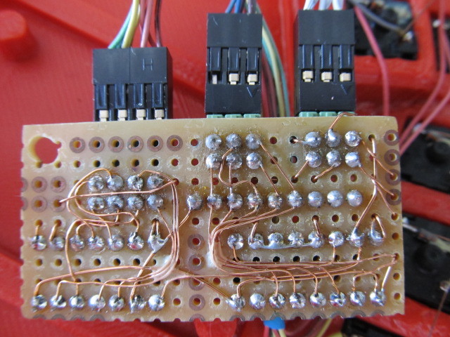
universalPcb.jpg
universalPcb.jpg (107.76 KiB) Viewed 16431 times
Even in this case I would recommend to draw the PCB (probably with a lot of layers so that you can cross wires) in Kicad. This way it will show you which pads to connect together. Kicad will check your PCB so that it corresponds to the schematic. You do not want to connect wrong pads. It would be hard to find the error.

@kiltannen, CrimsonFlame:

As for as the bootloader. My plan is modify the standard ATxmega DFU bootloader so that it does not check for pin PC3 pin and use that. The standard DFU bootloader is activated when external reset happens (i.e. the reset button is pressed) and PC3 is pulled to ground. The bootloader intended for Katy will ignore the PC3 condition and activate itself when one rests it with the button. I did not compile the bootloader yet (if you want I can try to do it this week). But even the standard bootloader binary is acceptable. PC3 is assigned to oLoad. You wold make a special RJ45 plug which has connected oLoad (RJ45-pin6) and GND (RJ45-pin7) through a 1-10 kΩ resistor. Connect the special plug; reset keyboard with the button; upload firmware; disconnect the keyboard; disconnect the plug and connect the left and right sides normally; and connect the keyboard.

ATxmega128a4u I bought did not come with bootloader preloaded. I'm guessing ATxmega64a4u would come with the standard bootloader preloaded. My guess is based on the "Atmel AVR1916: USB DFU Boot Loader for XMEGA [APPLICATION NOTE]" which mentiones ATxmega64a4u but not ATxmega128a4u. I plan to buy an ATxmega64a4u to verify this. If ATxmega64a4u comes with a bootlader then it may be a better option since its FLASH should be big enough for foreseeable future and one does not need some gadget to burn the bootloader first. One of the cheapest options to get a new bootloader to ATxmega seems to be this:
https://ketturi.kapsi.fi/2013/05/progra ... p-avrdude/
I use AvrDragon since I need a debugger too.

@CrimsonFlame:

It should not be a problem to add right hand side shift register support to EasyAVR to keep the right/left hand side connection within the 8 wires of an ethernet cable.
The LCD is FDCC0802C-FLYYBW-51LK.
As for as BOM. I can do only ATxmega version of BOM. Not sure whether you will go ATmega or ATxmega way now. I'm not in a hurry with BOM since it seems you and kiltannen will actually need a somewhat different BOM than I.

Shipping rates of some companies are crazy. E.g. 7bit can deliver from Berlin to Slovakia for 2€ (no tracking). There are businesses in Germany who are asking 70 € for shipping (probably with tracking). Shipping with tracking should be about 10 € or even less. E.g. Farnell wants 5€ for shipping with tracking from UK.

CrimsonFlame

06 Jul 2015, 20:45

@vvp:
I'd be interested in seeing if the ATxmega64a4u will work. I have a USBtiny ISP, so I'll have to dig into the article you linked and see if the patch will work for my programmer (I believe the USBtiny is based on the USBasp). There's a chance a fellow at work has a Dragon I can borrow, so I'll inquire about that route.

Thanks for the LCD part num. It looks like Kicad is back up, so I'll put together a BOM.

@kiltannen:
I might be doing a run of the ATxmega PCBs via OSHPark, and if I do, I can stuff one and send it to you. As above, I might not be able to program them, but I'm gonna dig in and see if I can update my programmer to work with the ATxmega. I am pretty good with SMT soldering (I do RF electronics for work), so I've done everything up to TQFP. I haven't dared to try BGA level tech yet.

---

I'm also looking at using mini-DisplayPort cables as a cheap 16 conductor link. I have a friend who's sending me a couple miniDP sockets, and I've whipped up a simple breakout that I should be able to fit in the same slot as the RJ-45s. I've been kicking around the idea of using the mux, and leaving some of the extra lines on the mDP link to shoehorn in a second LCD driven by LCDproc to give me system stats. And maybe a USB hub. We'll see how ambitious I get.

Another status update: I've now gotten both keywells and base plates printed. Printing the left palm part now, and hopefully the right one after that. I need to run into town and pick up some acetone for ABS glue. Gotta watch those outer walls when you are clearing the keywell supports. Be patient and don't rush or get too excited.

Not sure if I've said it, but thanks for sharing your design and ideas vvp!

CrimsonFlame

06 Jul 2015, 21:00

@vvp: Are you using KiCad on windows? I'm running into an issue loading the kicad project, and it appears to be a new "feature", where case sensitivity was introduced on *nix systems, but not in the default windows builds. I'll try loading the project on a Windows version of KiCad as soon as I can.

User avatar
vvp

06 Jul 2015, 22:16

I'm using kicad-bzr on archlinux.

> pacman -Qi kicad-bzr
Name : kicad-bzr
Version : r5648-1
Description : Electronic schematic and printed circuit board (PCB) design tools
Architecture : x86_64
Build Date : Sat 09 May 2015 02:16:01 PM CEST

If you want to try a windows version try as new version as possible.
I can also easily update to kicad-bzr-r5884-1-x86_64 (kko built the package yesterday) and check if the problem is there. Let me know if there are any tests you want me to do with r5884. I'll update to r5884 sooner or later anyway.
https://code.launchpad.net/~kicad-produ ... -revisions

I'll definitely add ATxmega64a4u to my next order and build a breakout board to test whether it has a bootloader by default. Although, the result will not be known sooner than 2 weeks ... or maybe a month.

User avatar
vvp

06 Jul 2015, 23:02

One more tip. If you have a problem with wall delamination when cleaning the support then paint just the walls with acetone even before cleaning the support. They will be probably painted only from the outside where they are accessible but it will make them stronger. Paint the whole part with acetone again when all the support (and strings if any) is cleared.
Good acetone painting will improve the strength of the part a lot. This also means that un-removed support (or strings) will hold better when painted with acetone. So do not paint the support (or the strings if any) when they are still on the part.

After it is cleaned up, it would be just easier to submerge it in acetone for about 2 seconds a pull it out and shake it a bit to remove excess acetone. But I do not want to contaminate so much acetone with ABS plastic. Also when painting I put a bit of acetone which will be used for painting into a small separate container because it will get contaminated from the ABS on the brush.

The walls will be strong plenty enough after key and palm parts are glued and the RJ45 (or your DP alternative socket) is glued into its slot.

Do not pour dirty acetone directly into a drain. Home drain pipes are often from some version of ABS. They could melt. And work with acetone in a well ventilated room or outside. It stinks badly.

Post Reply

Return to “Workshop”