(Model MF) Remodeling the Model M (aka.. the Mara)

User avatar
lot_lizard

29 Aug 2016, 12:01

DMA wrote:
lot_lizard wrote: I am going to experiment with latex film under the PCB. It can be as thin as .15mm (going up in small increments). I would like something under our thin PCB anyway to further deaden ambient vibration, and it also provides the perfect means of separating the plate assemblies (sits directly above the bottom plate).
While you're at that - can you please check how thickness of that affects key signal (detection stability, pressed/released levels..)?
Will do... Glad you asked, because I would have skipped that kind of detail and just performed a "still works?!?" test. It would be good knowledge to have on hand.


@Wodan... I always wondered what happened to Brandon from Punky Brewster. It's good to see he found a second career.

User avatar
lot_lizard

29 Aug 2016, 18:27

So I went back to some of the sound dampening ideas since foam is next. Aside from the floss mod, there are two things we can do that actually are very interesting. When I tried, it certainly has impact.
  • Adding a dampening sleeve to the outside of the barrel at its base (above the top plate). This deadens the click of the spring slapping the barrel a fair amount even with my simple o-ring test... Say 20%
  • Adding an o-ring to the inside of the keystem, to act as the point of contact when the key bottoms out had significant impact. Obvious the more you deaden, the shorter the throw, but 1mm rings don't interfere with the mechanics of the switch at all (what I had on hand, but would like to test at say .5-.8mm)
I would need this on several keys to actually develop an opinion, but it does certainly quiet things. Instead of sourcing rings and sleeves, I would just use the laser cutter and make them be ideal fits. Make the sleeve extra thick and notch for the barrel locks, etc. Moral... Needs more testing, but was more promising than expected
O-ring inside the stem
image.jpeg (1.07 MiB) Viewed 5763 times
Couple of o-rings wrapping the barrel
image.jpeg (953.35 KiB) Viewed 5763 times

User avatar
drevyek

29 Aug 2016, 21:26

Great work! Pretty simple to implement, too. For the barrel sheaths it would be interesting to play with both with and circumference of the rings- does a tighter, thinner ring make it damp better? A thicker, but looser ring? Would using foam between the barrel and the o-ring do anything? I'd test myself, but I'm away from home.

On silencing the up and down stroke, where in the barrel does the stem contact when on the up-stroke?

User avatar
lot_lizard

29 Aug 2016, 21:46

drevyek wrote: For the barrel sheaths it would be interesting to play with both with and circumference of the rings- does a tighter, thinner ring make it damp better? A thicker, but looser ring? Would using foam between the barrel and the o-ring do anything? I'd test myself, but I'm away from home.

On silencing the up and down stroke, where in the barrel does the stem contact when on the up-stroke?
To be honest, there is really zero reason you couldn't have a 5mm rubber liner (underlay) covering everything with additional cutouts to avoid the stabilizer bars. This would BY FAR be the best move all the way around, but does sacrifice appearance of the top plate if colored as an underlay (not a big deal to me, but might be to some). To rephrase, foam layer under the top plate with a thick rubber blanket above it.

Unfortunately, there is just quite a bit of sound that will come out of the keys themselves with those big barrel cavities, and no way to avoid it without a complete switch redesign.

On the upstroke, the sound really comes from the paddle returning from the PCB to the barrel roof, and the spring over-traveling to hit the back of the barrel. No way to really alter this much without effecting the switch performance. The keystem tops out on the tiny little pegs on the side and base of the glide. They are so small already that it wouldn't have much impact. Also, to answer your actual question... the stem tops out in the barrel on the ~45 degree triangle clips just above the flipper cavity (scroll back a few posts to see the underside of the barrel to make sense)

These dampening sleeve/line and rings have no impact on the switch mechanics itself, other than the bottom out is now higher in direct proportion to the CS of the o-ring at the top of the cap (which I kind of like the more I smurf with it). Essentially these are the equivalent of Cherry/Topre silencers... same concept.

EDIT: Just to be clear, the sleeve around the barrel base is never touched by the key (bottoms out above). It is solely there to quiet spring slap in the barrel. It helps on the return spring slap on upstroke as well but most of that sound comes from the spring reverberating up through the barrel cavity itself (not the striking of the barrel).
Last edited by lot_lizard on 30 Aug 2016, 00:00, edited 1 time in total.

User avatar
Techno Trousers
100,000,000 actuations

29 Aug 2016, 23:11

Interesting stuff. It seems like o-rings on the outside of the barrel wouldn't work well with AT style barrels, though? Wouldn't they also get in the way of Phosphorglow-style LED(s)?

User avatar
lot_lizard

29 Aug 2016, 23:18

Techno Trousers wrote: Interesting stuff. It seems like o-rings on the outside of the barrel wouldn't work well with AT style barrels, though? Wouldn't they also get in the way of Phosphorglow-style LED(s)?
There was a lot of fluff in the last couple of posts, but I would cut my own o-rings (or full liner). They would have notches for the AT lock. For the LEDs... his layer would sit over the rubber liner. I would have to check with him to see the thickness required, or if he had a planned route for the wiring, I just make a cutout for it. Still needs work for sure, but the liner makes the most sense, no question (if you want sound deadening, personally... I like it as-is). But it does sound nice muffled around every part but the actual switch. It could grow on me

User avatar
phosphorglow

30 Aug 2016, 00:36

So - I've just about got my new style lock indicator LED setup up to par. Instead of the annoying and time consuming way I did it before (very thin wires soldered to surface mount leds attached to custom mylar holders) the new way uses thin flexible circuits. Thin wires will still be needed, but won't be nearly as annoying as they were. These still sit on top of the frame, so no need to change anything for Phase 1.

Also... Send me some good mojo and wish me luck that I don't screw anything up, but I *might* be making some cast resin replicas of the SSK case. It'll take me through the rest of the week to complete the molds, so next weekend I'll (hopefully) be casting the first one.

Needs another layer of silicone, and then I can pour a plaster shell, flip it over, do it all again, and then start working on the bottom shell.
Spoiler:
2016-08-29 18.15.59.jpg
2016-08-29 18.15.59.jpg (59.39 KiB) Viewed 5614 times

User avatar
E TwentyNine

30 Aug 2016, 00:51

phosphorglow wrote: Also... Send me some good mojo and wish me luck that I don't screw anything up, but I *might* be making some cast resin replicas of the SSK case. It'll take me through the rest of the week to complete the molds, so next weekend I'll (hopefully) be casting the first one.
Awesome.

Sending mojo...
Image

User avatar
emdude
Model M Apologist

30 Aug 2016, 00:54

phosphorglow wrote: Also... Send me some good mojo and wish me luck that I don't screw anything up, but I *might* be making some cast resin replicas of the SSK case. It'll take me through the rest of the week to complete the molds, so next weekend I'll (hopefully) be casting the first one.

Needs another layer of silicone, and then I can pour a plaster shell, flip it over, do it all again, and then start working on the bottom shell.
Spoiler:
2016-08-29 18.15.59.jpg
Oh wow, that's pretty ambitious! :o Best of luck, looking forward to seeing the fruits of your labor. :)

User avatar
lot_lizard

30 Aug 2016, 01:26

It took me a while searching... But I've located Phosphorglow's high school yearbook picture (see below). I've learned... It's best to stay out of the way, put on a lead vest and protective eyewear, and wait for MAGIC!!!. Good luck my friend
image.jpeg
image.jpeg (193.28 KiB) Viewed 5548 times

User avatar
lot_lizard

30 Aug 2016, 02:09

In the spirit of happy and wonderful, a perfect little package was delivered today. Let plastic prototyping begin (without 2+ week delays). It fits famously in its new home
image.jpeg
image.jpeg (1.2 MiB) Viewed 5636 times
Last edited by lot_lizard on 30 Aug 2016, 08:54, edited 1 time in total.

User avatar
Wodan
ISO Advocate

30 Aug 2016, 07:13

If you want some first hand advice for the Ultimaker:
Get some Kapton tape for that glass plate. Platform adhesion has never been an issue for me since I did that. First patch still in place after 50+ prints. If you can, very wide Kapton tape so you can cover the whole printable area in one piece and don't have edges all over the platform.

User avatar
lot_lizard

30 Aug 2016, 08:52

Wodan wrote: If you want some first hand advice for the Ultimaker:
Get some Kapton tape for that glass plate. Platform adhesion has never been an issue for me since I did that. First patch still in place after 50+ prints. If you can, very wide Kapton tape so you can cover the whole printable area in one piece and don't have edges all over the platform.
Appreciate the tip.. I have some painter's tape sheets from a non-printer project laying around that are larger than the surface, and was going to try that to start. Will order some Kapton today


For those of you wondering this is all about: Kapton vs. Blue Painter’s Tape

User avatar
lot_lizard

30 Aug 2016, 10:47

Updated the foam layer for our isolated barrels (top row, bottom row, etc of keys). Pictures at the base of this post.

This is going to be a bit of a long read, but wanted to explain "why on earth" are we making this with mixed materials (it's not just about costs... would only add a couple dollars more to make it a consistent material that blocks sound better).

This layer (and the original foam) has two distinct purposes, listed in order of importance:
  • Secure/stabilize the keys - Because we are curved plates that look like swiss cheese, and the holes aren't in a uniform pattern, it is conceptually impossible to have even pressure applied across all barrels as the top plate is flattened to match the radial bend of the back plate. The top plate HAS to have shorter radial bend (more curved) than the bottom plate to assure the middle rows receive pressure because of manufacturing inconsistencies. IBM did this as well, and one of the reasons putting F assemblies back together takes force... not just about compressing foam. Its slight, but they are different curves even in the legacy design.

    In steps the foam... To account for inconsistencies between the rows, IBM used foam that if measured on the durometer scale (principal means for measuring hardness in polymers to save a click) would have been very low under even under compression. Their other mass produced material that compresses would have been rubber, which at the time was primary only produced on the complete other end of the durometer scale (hard). Since something too hard couldn't apply even pressure, they really only had one choice.

    We are very lucky in that polymers are now produced readily in the middle of the scale (say silicon, but there are a host of others). Durometer of something nonporous does not change under pressure (it displaces). So with flexible rubber, we can much more easily apply even pressure as the plates squeeze together. Rows with a slightly taller gap between the plates receive very similar pressure to those that are tighter... the rubber displacement just varies. Now our barrels are not only secure, but also consistent. The real experiments with the barrel "silicon foam" part is not going to be about the material used, but the durometer of the material that yields the best result. Using Wodan's individual "foam" idea, we can also assure that each barrel in the row is granted the same displacement because it can now spread on both axes consistently (assuming they are gapped enough to displace)
  • Absorb unwanted noise - foam does not block sound, it absorbs (why it is used in recording studios to prevent echo). The frequency of the sound (given amplitude) that is absorbed can be controlled however and tuned. The higher the frequency, the easier it is absorbed because it has to make more wavelengths to go the same distance as a lower frequency (travels more to go the same distance to rephrase). This is why you here bass coming from the neighboring vehicle at the traffic light, but not much else. Our goal is to tune the pitch to make the effect as "crisp" as possible (not quiet). Again, tons of sound will come out of the barrel cavity through the key itself regardless of what we do.

    Because tuning the sound is less important than holding the barrels consistently (which effects the pitch of each key), we will want to use a material between the keys that is a lower durometer under the same compression, and would never absorb as much of the frequency range as we theoretically could. The more you compress a material that is porous, the higher its durometer becomes, and thus the wider the range of frequencies it can absorb (always starting from high to low). The experimentation is to see how close we can match the durometer of these two "layers" without ever equally or surpassing that of the barrel stabilizing "layer". Remember that the stabilizing material needs to displace, and it will occupy the space of the softer material under compression
Sorry that was so wordy, but wanted it to make sense and not look like over-architecture for the sake of it. I have a feeling folks were wondering why we were designing "soles for a new line of running shoe", to which these similar concepts apply.

Below are the pictures of the updated "foam" components (really rubber of varying hardness and porosity)
New "stabilizing" layer to hold barrels that don't have another barrel immediately lower than it
Screen Shot 2016-08-30 at 3.37.15 AM.png (58.48 KiB) Viewed 5548 times
"Sound" layer updated to account for the new stabilizer
Screen Shot 2016-08-30 at 3.41.27 AM.png (86.69 KiB) Viewed 5548 times

andrewjoy

31 Aug 2016, 16:23

Wodan wrote: If you want some first hand advice for the Ultimaker:
Get some Kapton tape for that glass plate. Platform adhesion has never been an issue for me since I did that. First patch still in place after 50+ prints. If you can, very wide Kapton tape so you can cover the whole printable area in one piece and don't have edges all over the platform.

Just print in PETG , all you need then is simple glue stick , its stronger than both PLA and ABS and does not require the bed to be as hot.

E3D in colab with SpoolWorks have a branded version called Edge that is suposed to be amazing.

http://e3d-online.com/Edge

User avatar
Wodan
ISO Advocate

31 Aug 2016, 16:38

Would really love to see more PETG filament. Got a spool from some Chinese vendor a while ago when this was still a novelty. But I am very sick of glue stick rubbing. What a mess on the glass plate after a few prints ...

It's really a different life once you got kapton on your glass plate. Just wipe it with some cleaning alcohol every once in a while and you're good. Glue stick residue tends to really build up to a point where you have to scrape it off. And the adhesion isn't even better than on kapton.

I wish I was closer to y'all and could send you just a few patches of kapton. Bought a whole roll of tape and only used a single strip so far.

User avatar
lot_lizard

31 Aug 2016, 17:08

andrewjoy wrote: Just print in PETG
...
E3D in colab with SpoolWorks have a branded version called Edge that is suposed to be amazing.

http://e3d-online.com/Edge
Thanks for the tip. I'll order some and try it. The big thing would be durability, and it seems to have properties very similar to ABS on that end (impact resistance with some flex). We will be screwing into the stabilizer clips from underneath, so we need it to secure well with sheet metal screws without worrying about cracking them (not exact dimensions, but example below).
0142706.jpg
0142706.jpg (6.76 KiB) Viewed 5440 times
Last edited by lot_lizard on 31 Aug 2016, 19:58, edited 1 time in total.

User avatar
Techno Trousers
100,000,000 actuations

31 Aug 2016, 19:39

I just wanted to pop in and say "thanks" for explaining the method behind your madness, lizard. I trust completely that you will end up at something that is as close to optimal as is possible with today's materials. It's really interesting to see the process at work as well... Sherlock Holmes style!

andrewjoy

31 Aug 2016, 22:17

lot_lizard wrote:
Thanks for the tip. I'll order some and try it. The big thing would be durability, and it seems to have properties very similar to ABS on that end (impact resistance with some flex). We will be screwing into the stabilizer clips from underneath, so we need it to secure well with sheet metal screws without worrying about cracking them (not exact dimensions, but example below).

PETG is far superior than ABS when it comes to bonds between the layers.

ABS just sticks to itself along the layer where PETG forms a chemical bond with the layer below , far stronger in that regard.

PETG has to be good quality and has to be kept dry , even more so than other filaments, if it gets damp and then is melted as the water molecule fucks with the polymer string and makes it brittle.

So stick with good quality brands at least for PETG, so go with the edge, they should sell it in evil ultimaker size as well.

Good brands for ABS and PLA are verbatim and esun respectively

I prefer verbatim as it works at more normal ABS temps, esun i have never used but it is supposed to be good however its ABS is a bit strange and prints at a lower temp, nothing wrong with that but it puts me off its PLA however is fantastic.


Off topic 3D printer talk.

I was servicing our Up Plus2 printers in work today as they have been used and abused for years. The amount 3D printers have moved on since 2013 is amazing! I mean the Up was not a cheap printer when it was new , hell it still sells for over 700 GBP and it has 3d printed parts in it! Its build area is tiny and its bed is held on by little metal clips that do nothing.

The Z axis guide on one of them has broken as its only a 3D printed item with a bearing pressed into it.

Its extruder is pathetic, its a tiny little plastic part ( injection molded ) that clips over the NEMA17 stepper no spring tensioner or anything.

The hot end however is the absolute dogs(that means good)! Its an all metal hot end , its super small super rugged, it can reach 300c without breaking a sweat in less than 2 mins, is the best thing about the printer hands down! They still use exactly the same hot end now on the brand new Up Box. Awesome!

But compare that to say , the Wanhao 6 , that thing has the all new MK11 extruder and hot end, has an enclosed build chamber and its all metal , not a single 3d printed part on it.

User avatar
Wodan
ISO Advocate

01 Sep 2016, 10:24

andrewjoy wrote: Good brands for ABS and PLA are verbatim and esun respectively
Oh yeah that reminds me of the most painful lesson I learned. Don't try to safe money on the filament. I really love to experiment around with things so when I got my printer I bought tons of different filaments (~15-30€ price range) and frankly they all sucked more or less. By far the best filament was the spool of PLA that came with the Ultimaker, gave me perfect results every time.

The time I wasted experimenting with cheap filaments and trying to get the temperature, thickness and feeder speed right is so useless. Get good filament, ideally one that comes with proper recommended settings for your printer and then MAYBE fine tune it a little and keep using the same filament unless it's crap. Nothing is more frustrating than walking into your workshop in the morning realizing the 12h overnight-print went bad 8h through the process because the nozzle was clogged.

andrewjoy

01 Sep 2016, 12:30

I had a similar experience with some cheap black ABS ( black abs can always be funny, it must the the additives to make it black). The stuff absolutely ruined both hot ends on a replicator 1 clone i had ( sent that piece of shit back and got the Wanhao i3). As soon as it gets hot it just goes very thin and sticks to everything , wave goodby to your PTFE liner. It makes excellent ABS slurry however :P.

This is part of the reason i want to move to an all metal hot end , the MK10 on the wanhao is nice but its got nothing on an E3D or a flexion system.

User avatar
Ratfink

01 Sep 2016, 15:47

Wodan wrote: If you want some first hand advice for the Ultimaker:
Get some Kapton tape for that glass plate. Platform adhesion has never been an issue for me since I did that. First patch still in place after 50+ prints. If you can, very wide Kapton tape so you can cover the whole printable area in one piece and don't have edges all over the platform.
Even better than Kapton tape: a PEI sheet. ABS sticks to it better than anything else I've seen. Plus, unlike with Kapton, you can get thick enough sheets that it can't tear.

andrewjoy

01 Sep 2016, 17:29

I should give PEI a try , its a PITA to have to use ABS Juice every time , but it does leave one hell of a mirror finish on glass.

But as i am switching to PEGT when my ABS runs out i dunno if its worth it as glue stick on glass is well enough for that.

User avatar
phosphorglow

03 Sep 2016, 10:35

So, I think the good mojo helped... ^_^

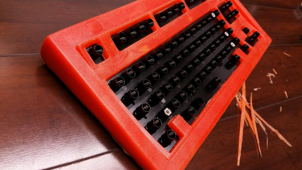
This resin is low durometer and semi-rigid and I didn't bother degassing it so there are a lot of bubbles, but I didn't care because I just wanted to see what problem areas I might run into with the mold... Plus, it was the only resin I had on hand at the time and I really wanted to give it a shot.

Anyways, the possibility of some custom cases appears to be reasonably attainable. I'll know in about 15 hours after the next casting (using a different resin) cures. If I'm happy with it I can start working on the bottom half of the case.

This is just plain silly:
Spoiler:
2016-09-03 03.52.33.jpg
2016-09-03 03.52.33.jpg (94.88 KiB) Viewed 5281 times
(For giggles and kicks I added some orange pigment to the resin. Just 'cuz.)
2016-09-03 03.52.00.jpg
2016-09-03 03.52.00.jpg (88.82 KiB) Viewed 5281 times
2016-09-02 03.45.381.jpg
2016-09-02 03.45.381.jpg (97.25 KiB) Viewed 5281 times

User avatar
emdude
Model M Apologist

03 Sep 2016, 10:41

Oh man! :shock: :o :oops:

User avatar
HAL

03 Sep 2016, 11:34

You, sir are a gentleman, a scholar and a sexy beast
Shut-up-and-take-my-money.png
Shut-up-and-take-my-money.png (133.61 KiB) Viewed 5248 times
Ok here is my order:
1 SSK shell in red
1 SSK shell in yellow

User avatar
HAL

03 Sep 2016, 11:38

On second thought I also desperately need a pink one :D

User avatar
lot_lizard

03 Sep 2016, 12:30

phosphorglow wrote: So, I think the good mojo helped... ^_^
Image
HOLY $HIT... That turned out fantastic, especially considering you didn't even pressurize.

I think it is safe to say it is VERY promising, and you will some pretty serious demand for it if you get denser resin to turn out this well. I'm eager to see the results 15 hours from now.

Extremely well done

User avatar
002
Topre Enthusiast

03 Sep 2016, 13:22

That is so cool! Especially for those people who don't have an SSK and were dreading the thought of having to find one.
Nice work, man.

User avatar
E TwentyNine

03 Sep 2016, 13:57

I'm sensing a new section on the phosphorglow website... Sell them color-coordinated with the underlays.

How does the inside look?

How do you suspect the wear/toughness of a "real" cast will hold up to daily use?

Post Reply

Return to “Workshop”