Generating DXF files

User avatar
7bit

17 Sep 2016, 10:59

Here is a DXF-file which came from kicad, has been cleaned up, scaled down to 1:1 and converted to mm:

Code: Select all

0
SECTION
2
HEADER
9
$ANGBASE
50
0
9
$ANGDIR
70
0
0
ENDSEC
0
SECTION
2
ENTITIES
0
LINE
8
BLACK
10
19.1262
20
327.27646
11
19.1262
21
398.40662
0
LINE
8
BLACK
10
18.9738
20
327.27646
11
18.9738
21
398.40662
0
ARC
8
BLACK
10
19.05
20
398.40662
40
30.0
50
360.0
51
540.0
0

...
<-- removed uninteresting stuff to make it smaller :o -->
...


BLACK
10
190.5
20
382.8415
40
450
0
CIRCLE
8
BLACK
10
228.6
20
382.8415
40
450
0
CIRCLE
8
BLACK
10
41.529
20
342.8365
40
450
0
CIRCLE
8
BLACK
10
227.2665
20
342.8365
40
450
0
ENDSEC
0
EOF
:roll:

My question:
Is this a valid DXF file. Loaded to the right machine, will it produce a mount plate for the Hyper Micro keyboard?
:?
Attachments
dxf.png
dxf.png (3.33 KiB) Viewed 2901 times
HyperMicro_7BIT_test.dxf.zip
(20.01 KiB) Downloaded 102 times

attheicearcade

17 Sep 2016, 11:43

This is what it looks like in eDrawings:

Image

If I zoom in and look past the circles I can see the keyboard outline and switch cutouts, but there are lots of overlapping and broken lines:

Image

User avatar
7bit

17 Sep 2016, 12:02

OK, thanks!

Seems Kicad is useless to produce anything meaningful.

What about this simplified file:

Code: Select all

0
SECTION
2
HEADER
9
$ANGBASE
50
0.0
9
$ANGDIR
70
0
0
ENDSEC
0
SECTION
2
ENTITIES
0
LINE
8
BLACK
10
75.0
20
75.0
11
900.0
21
75.0
0
LINE
8
BLACK
10
900.0
20
75.0
11
900.0
21
300.0
0
LINE
8
BLACK
10
900.0
20
300.0
11
75.0
21
300.0
0
LINE
8
BLACK
10
75.0
20
300.0
11
75.0
21
150.0
0
ENDSEC
0
EOF
It is in no specific measure, just need to know if this works out.

It should look like a rectangle wherr the left side does not come close to the start point.

attheicearcade

17 Sep 2016, 14:26

Looks to be fine:

Image

User avatar
7bit

17 Sep 2016, 14:56

OK, Thanks!
:-)

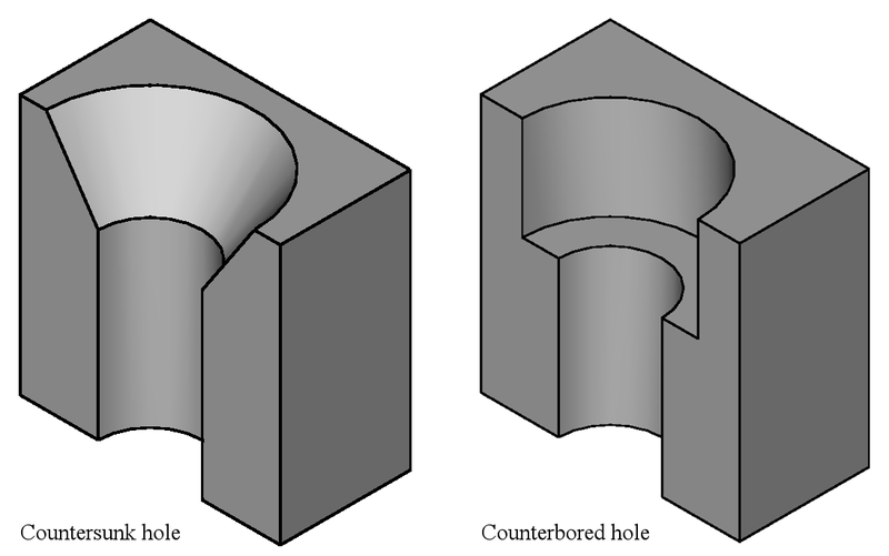
Do you know which command to make something like in the left picture?
Image
:o

attheicearcade

17 Sep 2016, 15:55

As far as I know you won't be able to do that since it is a 3D feature and dxf is for 2D geometry. Generally I would put the hole diameter and then just call out the countersink in a drawing.

How do you want to get this manufactured? (what material and processes)

User avatar
7bit

17 Sep 2016, 16:08

The mount plates will be made of steel. Those countersunk holes are just a feature that is not technically necessary, but would look more elegant.

BTW: The file I posted whth the rctangle, that would really cut such a rectangle, or would there be anything missing to make sure the machine can do it?

If it really works, I'm quite sure to be able to write the tool within a day and to get the DXF files out for production should take no longer than a week.

Thanks so far!
:-)

attheicearcade

17 Sep 2016, 17:56

No problem 8-)

I'm guessing you'll be using a laser cutting service, so the countersink will be a separate operation, but for one keyboard it shouldn't be too much. Just point out which holes need countersinks when you send them the files.

Depending on where you send it you will get different responses, some places like proper drawings and won't accept anything else, some will work off pretty much anything: word descriptions, hand sketches, dxfs. The best thing to do is to ring them up and ask if they will accept a dxf.
When you are generating the dxf just try to make sure there are no tiny gaps between what should be continuous lines. I recommend DraftSight (free AutoCAD clone) for any quick 2D drawing stuff, I think it has a check closed contour tool.
You couldn't send them that rectangle one because you need a closed contour on the outside, or they'd have to send you the entire sheet :)

User avatar
7bit

17 Sep 2016, 18:25

Be sure, when my script generates those lines, there will be no gap at all!
:P

I don't need any GUI tool, except GNU Emacs, because I will generate the files from a similar source as the key caps mockup graphics. A GUI would not be helpful, because I don't want to draw any lines manually.
:o

Also, the reason I do this myself is because Kicad changed its file format and the old version can't output DXF files properly, as I can see in the graphic above. A different tool would be in the way.

But thanks a lot for your help!
:ugeek:

BTW: I've found 2 sources that describe the file format:
http://www.fileformat.info/format/dxf/s ... a/view.htm
and
http://images.autodesk.com/adsk/files/a ... ce_enu.pdf
:mrgreen:

Just to have this in one place:
https://www.ucamco.com/files/downloads/ ... cation.pdf
:?

attheicearcade

17 Sep 2016, 19:21

I mean you can use that package as a sanity check for your script, they also do a Linux version :)
7bit wrote: GNU Emacs
I tried to switch to emacs with evil mode just last week for a particular plugin. Ended up getting frustrated because I was rushing, so I ended up back in vim. Maybe one day...

User avatar
7bit

17 Sep 2016, 19:29

He, he! I must pretend, my appreciation for commandline tools would match better with vim than emacs, but then nobody is perfect!
:-)

Post Reply

Return to “Workshop”