WYSE Converter

User avatar
Soarer

08 Feb 2014, 16:41

Introduction

This firmware for Teensy 2.0 etc. aims to convert all WYSE terminal keyboards which have a 4P4C connector, to USB.

See Wyse keyboard protocol (4P4C) for more information about the protocol and the models that use it.

(There's also a thread for this project on GH).

Features

All of the configuration features of my XT/AT/PS2/122 Converter and my Keyboard Controller firmwares are supported (remapping, layers, macros etc).

At start-up, the converter automatically determines which WYSE keyboard is attached by reading an ID byte. Also, a basic check is performed to try and prevent damage in case the connector or cable has been wired in reverse.

LEDs on the keyboard are supported. PCE and AT-style have all 3 lock LEDs, whereas the 285 just has Caps and Scroll.

Hot-swapping of the keyboard is not supported, but might be in a future version. Until then, always connect the keyboard to the converter before connecting the converter to the computer.

Use hid_listen to see what the converter is doing - for example to diagnose any problems at start-up, to check key codes for remapping, etc.


Models supported

Code: Select all

Model             Keys  Part Nos (old, new/white)  ID (hex)          Status
---------------------------------------------------------------------------------
30                 83   840013-01                  01                Should work
60 ASCII          101   840338-01, 901867-01       41                Verified
60 ANSI           101   840338-09                  41                Verified
60 3161           106   840338-02                  04 (or 05/06/07)  Verified
85                105   840105-01                  n/a (00)          Verified
85 Gate Array     105   840366-01, 901879-01       60                Should work
285/520           108   (841038-01), 901028-01     62                Verified
285/520 ANSI WPS  108   (841038-06), 901028-06     ??                Might work
AT Standard        84   840275-04                  02                Should work
PCE US, Grey      102   840358-01, (901865-01)     82                Verified
PCE Int'l, Grey   103   840362-01, (901866-01)     83                Verified
PCE US, White     102   840358-13                  82                Verified
PCE Int'l, White  103   840362-04                  83                Verified
PCE US            102   (841135-01), 901865-01     82                Should work
PCE Int'l         103   (841135-02), 901866-01     83                Should work
Note: WY85 is not the same as WY85 Gate Array - they're the same outside, but very different inside! I think WY85 Gate Array is the more common, and later, version.

For WY50 see here, and use my Controller firmware.


Connections
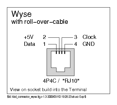
Image

Note: this is looking at the front of the socket that you might fit to your converter. The socket on the keyboard (for those with a removable cable) is a mirror image of this diagram; the cable is wired as a 'cross-over' type.

For both ATmega32U4 and AT90USB1286, connect as follows:
Data -> PD0
Clock -> PD1
+5V -> VCC
GND -> GND

Lock LEDs can be wired to any Pxx pin, and defined in your config file. An example config is included which sets up lock LEDs which are active high on pins PD5 to PD7 (i.e. the same as my XT/AT/PS2/122 converter uses on ATmega32U4).
wikipedia modular connector wrote:The 4P4C connector, is popularly, but incorrectly, called RJ22, RJ10, or RJ9. It is also commonly referred to as a handset connector because the most popular usage for the connector is to terminate both ends of a handset cord and it is the de facto standard for this application.
So, for the models with a removable cable, if you need a replacement cable, or want to hack a cable to make the converter, handset cables are easy to find and cheap.

There are also various handset adapters (for recording, etc.) that could be a good source of the correct socket already mounted on a PCB and boxed. Finding one with enough space to fit a Teensy or Pro Micro inside shouldn't be too hard. This method might well require some hacky wiring onto the connector's pins (but that would be hidden anyway), and of course removal of other components on the PCB or tracks cutting (probably trivial).

Beware that some handset adapters have an RJ11 (6P4C), which isn't what you want! I've no idea what they are for. It's difficult to tell 4P4C and 6P4C apart just by looking at the photo of an item.


Resistor

Resistor is optional if you don't want to use a WY85 (non-gate array).

WY85 (non-gate array) requires a pull-up resistor between Data and +5V. The ideal value is 2.2k, but any value between 1k and 4k should work fine. The pull-up resistor does not interfere with any other WYSE keyboard models.


Tools

Use the tools from my Keyboard Controller, v1.20 to assemble and write your config files to the converter.


Config

There are no new config commands or extensions to existing commands specific to the WYSE keyboards as yet, but there are some on the to-do list:
  • extend the 'ifkeyboard' and the 'ifset' commands to cover the various models
  • allow the pins used for Clock and Data to be specified
  • add an option for the 285's Scroll lock LED to show Num lock status (or hard code it)
Downloads

ATmega32U4 (Teensy 2.0 etc) and AT90USB1286 (Teensy++ 2.0) are currently supported.

Note: if you are re-using a Teensy or other board, load the .hex before connecting a WYSE keyboard.
Attachments
Soarer_WYSEverter_v1.30.zip
(41.76 KiB) Downloaded 828 times

User avatar
Muirium
µ

08 Feb 2014, 19:36

Sterling work as always, Soarer! I'll see if I can borrow back a WYSE ASCII to try this out on.

The fact you're always bringing along the full firepower of your previous work is genius, as we can instantly do the same. One Soarer's Converter is enough to learn them all!

What are the chances, I wonder, of you supporting the M0110 original Mac keyboard (which uses the same 4P4C connector as the WYSE) and ADB someday? I could put both of those to instant use. Even better if I could get my unicorn wish of combining the two into a single box! The XT/PS2/RJ45 hat trick has really spoiled me.

Hasu's amazing polyglot of a firmware is ready for me to try on both counts, of course. But I've become quite adept at speaking Soarer, or fluent enough for my needs.

User avatar
Soarer

08 Feb 2014, 20:30

So supporting a dozen or so keyboards with 8 different matrix layouts in one converter isn't enough for you?! :lol:

There are differences in the way WYSE / IBM / ADB drive the lines that make them fundamentally incompatible, and even without that, auto-identify might cause issues. A future Soarer might allow connecting both IBM and WYSE to the same Teensy, but on different pins, so you might then be able to have a box with all the sockets at least!

Not sure about M0110 and/or ADB since I only have one ADB keyboard to test with, and it's an awkward protocol to get right (i.e. broadly compatible).

User avatar
Muirium
µ

08 Feb 2014, 20:41

Give an inch, and they will take a mile! So beware when you give a mile in the first place.

ADB's a tricky one, all right. No separate clock and data lines, and devices negotiate their address on the bus. Woz was a sly bugger back in the day…

trans

03 Sep 2016, 06:16

Anyone make a rj10 to teensy adapter?

iceberg

10 Oct 2017, 00:00

Soarer, thanks.

Do you, or anyone here for that matter have any experience troubleshooting a flaky keyboard?

I have a 840358-01 and it has a WYSE branded 211001-02 507 chip and a 74HC163N counter.

Problem: starting with the column "-" and all the way to the right as well as all the F-keys do not work.

I've tested continuity from both sides of all the switches to the IC and that is good. I don't currently have anything to read the DATA pin of the chip without writing a new program for the teensy. I have a PI bit it's not with me at the moment and later this week I might be able to go to storage and grab it. So I'm wondering if anyone has any ideas in the mean time.

Thanks to anyone that might have some advice.

User avatar
snufflecat

03 Nov 2018, 14:15

Hi there :) I'm working on converting my WYSE-board, but from what I've understood I have to make my own config file? In that case, is there any "boilerplate" that I can use, or do I have to start from scratch? And if so, where do I begin..? I've tried looking into the documentation, but well, it's confusing..

User avatar
Hypersphere

03 Nov 2018, 16:02

@snufflecat: Which Wyse board do you have? Does it have a detachable 4p4c cable? If so, you could get an orihalcon-Soarer converter cable. You could use just about any *.sc file as a starting point.

User avatar
snufflecat

05 Nov 2018, 13:52

Here's some pictures of the PCB etc.:
https://imgur.com/a/FDDKT2X

Looks like the model isn't included in the list, as far as I can tell. I guess this means .. I have to start from scratch?

User avatar
zrrion

05 Nov 2018, 17:54

Doesn't the converter identify the board at startup? You might be able to force it to skip identification if it doesn't know what that one is. Then you force it to act as if it is converting a similar board and hopefully that will get you close enough.

User avatar
snacksthecat
✶✶✶✶

05 Nov 2018, 17:59

One thing that's tricky about the wyseverter that has thrown me off in the past; I believe you have to flash the microcontroller while it is detached from the keyboard. In my experience, if you flash it while connected to the keyboard, the converter doesn't work.

User avatar
snufflecat

10 Nov 2018, 23:23

Alright, here I am again with yet another bunch of overly complex questions since I really don't know what I'm doing..
So I took my sweet time, pulled out the multimeter, and tried tracing each of the two contact points (solder points) of each switch to see what pin they were connected to.

I mapped everything out in a spreadsheet, where the rows correspond to the number on the pins:
Capture.PNG
Capture.PNG (68.46 KiB) Viewed 18640 times
Picture of the underside of the chip, for reference (please ignore the "lead dust"):
chip.jpg
chip.jpg (668.45 KiB) Viewed 18640 times
Questions:
1. Did I do this correctly?
2. Should I get contact twice on every switch? At least one (N_0) only registered once, but a lot of the other switches registered twice.
3. Now.. where do I go from here? How do I turn this into a working config file?

User avatar
zrrion

10 Nov 2018, 23:58

What you should do probably is start a new thread, since it is looking like you won't be using Soarer's converter. (unless someone adds that board to the converter)
For your immediate question, you should notate which solder point on the switch goes to what pin. That way you can figure out what the rows and columns are. Once you know the rows/columns you can desolder that controller chip, wire a teensey up, and flash it with TMK or something.

User avatar
snufflecat

11 Nov 2018, 20:19

zrrion wrote: What you should do probably is start a new thread, since it is looking like you won't be using Soarer's converter. (unless someone adds that board to the converter)
For your immediate question, you should notate which solder point on the switch goes to what pin. That way you can figure out what the rows and columns are. Once you know the rows/columns you can desolder that controller chip, wire a teensey up, and flash it with TMK or something.
Alright, I'll do that, thanks. :)

User avatar
hellothere

06 Oct 2021, 02:56

wyse - Copy.png
wyse - Copy.png (4.29 KiB) Viewed 13155 times

Post Reply

Return to “Workshop”