Amazing stuff, I$. Thank you for the tutorials, your idea and all the work you did on this project.
After postponing it for so long, it was finally FSSK building time today

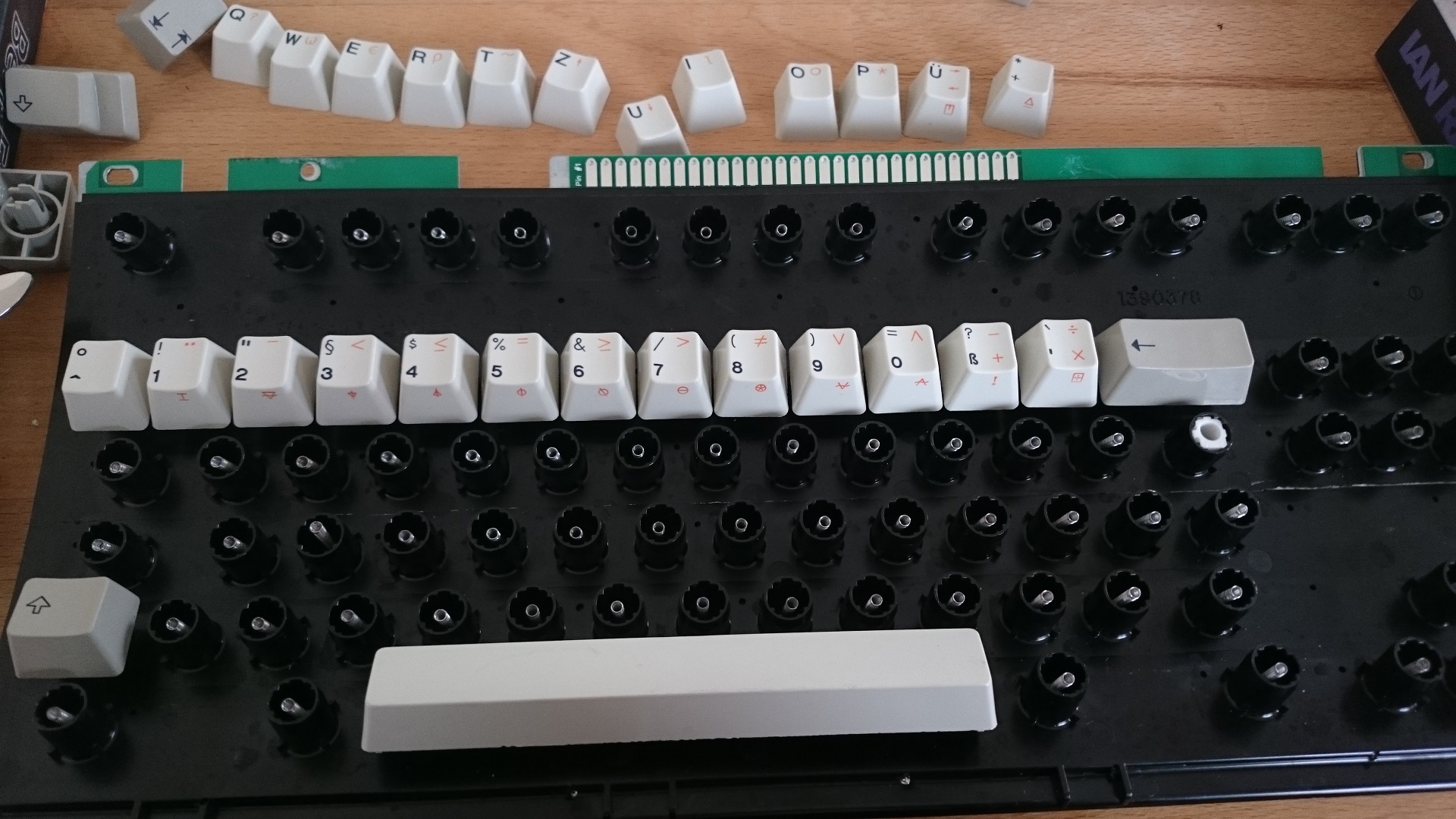
- DSC_0905.jpg (524.32 KiB) Viewed 23169 times
Following your advice from the other thread, I did not use the mat.
I have the IDE ribbon cable ready, all it needs now is a controller.
I wonder, do you think I can solder the cable to the holes without taking it all apart again? Maybe by bending the top part after heating it again so that I can reach both sides of the holes?
Anyway, I did a test run without a controller and it clicks 99% fine. There is one key that feels slightly rough/scratchy and one key that is a bit harder to press than the others, wobbly. I believe this is due to there being very few screws under that position to hold the flipper in place (it's the L key, turn it around and you will barely find any screws there).
Or maybe it is due to this beat up and glued barrel frame as you can see, it's just not as solid as a new one.
The feeling is amazing. Exactly what membrane IBM keyboards are lacking: Smoother, lighter keys and a sharper click.
But the sound... Oh my

That thing is beyond loud. Just like the SSK phosphorglow posted two years ago (the video is gone now) this little SSK has no rubber mat to dampen its sounds. And the flippers are larger and they snap right on the plastic of the PCB, instead of three sheets of membranes.
I'm not sure if I, my girl or my neighbors could ever get used to that sound. It's intense.
I do hope that I did everything right by leaving out the rubber mat? And not using any tape or other to isolate the PCB or the metal plate? As in the other thread, you said no isolation is needed...?


