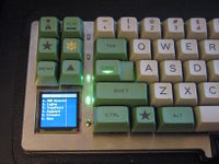
MX13 SpaceSaver Keyboard

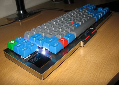
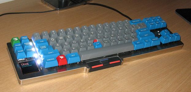
The MX13 SpaceSaver keyboard is a custom designed and built keyboard based on Cherry MX key switches and an IBM TrackPoint IV pointing device. The concept was inspired by the Miniguru keyboard made by Deskthority and Geekhack forum user lowpoly. The execution was also inspired by lowpoly and his hand-wired Apple M0110, along with Deskthority and Geekhack forum user matt3o's Steely and BrownFox keyboards and how-to guides.
Background
This keyboard was designed and built as part of the Laser Cut Prototyping mini-GB group-buy run by matt3o in September, 2013. The original concept was to create a Cherry MX based keyboard similar to the IBM SpaceSaver II. The name MX13 SpaceSaver is an homage to the IBM Model M13 keyboard (essentially a Model M with integrated TrackPoint), Cherry MX key switch, and IBM SpaceSaver II small footprint keyboard.
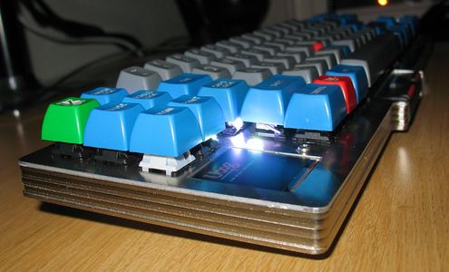
To reduce the keyboard footprint and number of components, the function keys F1-F12 were removed from the layout. This allowed for the remaining "top row" keys to be placed in a cluster on the left-hand side, which helps to balance the layout. With the remaining space, a 128x128 OLED display was added to the bottom-left corner to support keyboard configuration and diagnostics. Additional features include RGB key lock indicators (both in-key and plate mounted), num-lock support, configurable function layers, full programmability, and a detachable Micro-USB cable.
Most parts of the keyboard design and implementation are in the public domain and can be produced and improved upon by anyone. The parts that are currently known to be restricted are the tmk_keyboard firmware base, which is GPLv2, and u8glib graphics library, which is distributed under the new BSD license (and contains other, differently licensed graphics and fonts).
The hardware design and firmware customization was done by mtl, with the help and support of matt3o (also the group-buy organizer), Muirium, Vierax, Zifle, Broadmonkey, and IonutZ.
Pictures (more here)
Hardware
Case
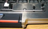
The case is comprised of 6 layers with a total height of 13.5 mm and an internal cavity height of 10.5 mm. The design file is here. The layout supports 76 keys, with the following characteristics:
- ANSI Enter key
- 7-unit space bar
- 1.5-unit Control and Alt keys
- 1-unit Super and Menu keys
- Center-stemmed caps lock key
- No FN1-FN12 keys
- FN keys are accessed by pressing FN+1 through FN+=
- Key cap profile considerations:
- Escape and Num-lock in row 1
- Pause/Break and Scroll-lock in row 2
- Print-screen in row 3
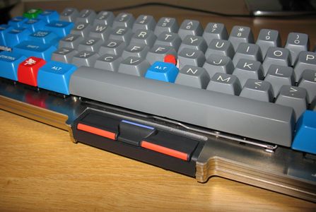
The TrackPoint stick is mounted on top of the switch plate.
This gives it the right height when used with SA-profile key caps produced by Signature Plastics.
If lower-profile caps are to be used, the TrackPoint will likely be too high.
To adjust the height, it may be possible to mount the TrackPoint stick below the switch plate and further recessed as necessary via washers.
This would require adding a center hole to the plate between the G, H, and B key switches for the stick to pass through.
| Layer number | Thickness | Name | Features |
|---|---|---|---|
| 1 | 1.5 mm | Top | Plate for mounting Cherry MX switches, TrackPoint stick, LEDs, window for display, etc. |
| 2 | 1.5 mm | Spacer 1 | Backing for ornament window above up arrow. |
| 3 | 3 mm | Spacer 2 | Cut-out for changing color sheet under ornament window. |
| 4 | 3 mm | Bridge | Support for TrackPoint button assembly, cut-out for Micro-USB port, wider screw arms for added strength. |
| 5 | 3 mm | Spacer 3 | Cut-out for Micro-USB port, wider screw arms and wider screw holes to accommodate brass inserts. |
| 6 | 1.5 mm | Bottom | Screw holes for mounting SpaceSaver II controller and LED controller boards. |
Version 2
A second iteration on the case design was made to address issues with the first version. The design file for version 2 is here. Note: This design has not been built and may contain errors. The following changes have been made from v1:
- Revised TrackPoint button bridge to fix design error and reduce impediments to button travel
- Removed 3rd (middle) stabilizer cut-out under space bar
- Moved stabilizer clip holes up 0.5mm to alleviate stabilizer slider friction
- Deleted unnecessary center TrackPoint support holes
- Moved top-right screw hole closer to USB port to better align layers near the USB opening
- Broke up loop around USB port to remove obstruction to wires when closing the case
- Gap for changing ornament color without having to open entire case (just loosen right-side screws)
- Moved TrackPoint buttons down 5 mm away from space bar for better comfort and widened bottom keyboard edge accordingly
- Moved display opening down 3 mm to make more room for it internally and better center it with new, wider bottom keyboard edge
- Recessed USB port 2 mm from keyboard edge
- Removed spring-swap holes for keys G, H, B, V, and N because those switches need to be dremeled to the point where they can not endure spring swaps
- Removed unnecessary button assembly lip cut into bottom layer
- Improved hole fitting for Tappex brass inserts
- Widened holes in bottom layer for 2 mm inserts from 3.5 to 3,7 mm
- Widened holes in bottom layer for 2.5 mm inserts from 4.3 to 4.5 mm
- Shrunk holes for 2.5 mm inserts on last non-bottom layer from 4.8 to 4.5 mm
- Added controller reset button hole below space bar
- Added an extra 5 mm breathing room under SpaceSaver II controller board
- Raised screw hole to the right of the space bar by 3.5 mm to allow greater clearance for stabilizer bar.
Key switches
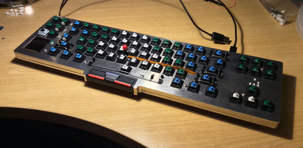
The keyboard design supports the use of all regular Cherry MX key switch types. For the prototype build, the switches were modified to use "clicky" blue, green and white stems, and a variety of spring types. The springs were chosen based on the force required to press them, the finger used to type each key, and in some cases, whether the key lies above, on, or below the home row. Additionally, a latching MX-Lock switch was used for the lower-left key, and is used in the firmware to enter keyboard configuration and diagnostics mode.
| Color | Spring |
|---|---|
| Red | Cherry MX Black or Green |
| Orange | Originative 65g |
| Yellow | Rapoo v7 Kaihua PG1511 (yellow) |
| Green | Originative 55g |
| Blue | Cherry MX Blue/Brown/Red |
Matrix
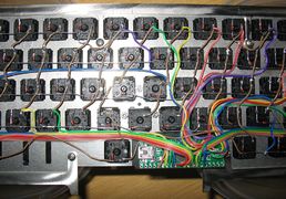
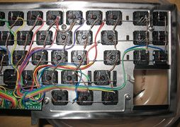
The switch matrix is wired as shown in the picture to the right. It can be wired differently, but that will entail corresponding adjustments to the firmware. The row connections are predominantly provided by the diode legs, although jumper wires are used in some locations to route around the case screw holes (e.g., between "2" and "3") and the longer gaps between key switches (e.g., between "alt" and "space").
The table below lists the matrix rows and columns, as well as the keyboard controller I/O pin assignments. The pin assignments are more or less arbitrary, but with consideration paid to pin locations reserved for special features of the Teensy controller and the physical layout of the Teensy circuit board.
| 0 | 1 | 2 | 3 | 4 | 5 | 6 | 7 | 8 | 9 | 10 | 11 | 12 | 13 | 14 | 15 | 16 | 17 | 18 | ||
|---|---|---|---|---|---|---|---|---|---|---|---|---|---|---|---|---|---|---|---|---|
| Row | Pin | E6 | D3 | D4 | A5 | E7 | D7 | E0 | E1 | C0 | C1 | C2 | C3 | F0 | F1 | F2 | F3 | F4 | F5 | F6 |
| 0 | A0 | escape | num- lock | ~ | 1 | 2 | 3 | 4 | 5 | 6 | 7 | 8 | 9 | 0 | - | = | back- space | insert | home | page up |
| 1 | A1 | pause / break | scroll- lock | tab | Q | W | E | R | T | Y | U | I | O | P | [ | ] | \ | delete | end | page down |
| 2 | A2 | config | print / sysrq | caps- lock | A | S | D | F | G | H | J | K | L | ; | ' | enter | ||||
| 3 | A3 | left shift | Z | X | C | V | B | N | M | < | > | ? | right shift | up | ||||||
| 4 | A4 | control | super | alt | space | alt | function | control | left | down | right |
- Close-ups of switch matrix wired to keyboard controller
TrackPoint IV
A defining feature of the MX13 SpaceSaver keyboard is the integration of a TrackPoint IV pointing device. The TrackPoint IV is the newest iteration of IBM's TrackPoint line and includes convenience features such as a middle mouse button, negative inertia, and press-to-select. The middle mouse button can be used in conjunction with the pointing stick to simulate a scroll wheel. Negative inertia (marketed under the name QuickStop response) contributes to more precise positioning of the mouse pointer. Press-to-select allows a downward pressure on the pointing stick to emulate clicking and dragging the primary mouse button.
IBM SpaceSaver II Keyboard
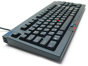
The IBM SpaceSaver II (SSII) keyboard is a great source from which to harvest IBM TrackPoint components for use in custom keyboards and keyboard modifications. The SSII uses a rubber-dome mechanism to implement its key switches and on that basis is not terribly interesting as an input device. What makes the SSII stand out, however, is the inclusion of a TrackPoint IV with sufficient height to be usable on so-called "mechanical" keyboards.
The only other TrackPoint IV product known to have sufficient height is the IBM TrackPoint USB Space Saver Keyboard. Other extant TrackPoint keyboards with sufficient height (e.g., the IBM Model M13, IBM TrackPoint II keyboard) are TrackPoint II devices, which lack the negative inertia feature of the TrackPoint III and the middle mouse button (used for scrolling) of the TrackPoint IV. All other known TrackPoint implementations are for low-profile keyboards, such as those used on ThinkPad laptops.
It also helps that the TrackPoint stick on the SSII keyboard is black, which looks nice, and the button assembly does not take up a lot of space. When selecting parts for the prototype build, other TrackPoint IV keyboards were surveyed (including those from ThinkPads), and the SSII button assembly had the smallest footprint as could be determined from pictures.
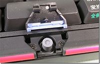
When disassembling the SSII keyboard, it is necessary to carefully remove the middle mouse button to access and remove two screws, as seen in the picture on the right. More information about the process is available here.
The TrackPoint stick is easily removable from the SSII and can be adapted to staggered Cherry MX layouts with some modifications to the key switches. The TrackPoint controller is implemented on the same circuit board as the SSII keyboard controller, however. So it is harder, if even possible, to physically separate, though the two circuits are powered separately and can be run independently. The approach taken on the MX13 therefore is to embed the entire SSII logic board, but only activate the TrackPoint portion.
SSII Controller Board
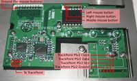
The solder connections for wiring up the SSII controller are pictured on the right.
In order to fit the SSII controller in the MX13 case while keeping a low profile, it is necessary to de-solder the tall, female ribbon connectors from the board.
There are two ribbon connectors for the keyboard matrix, one for the external PS/2 mouse input, and one for the TrackPoint stick.
The latter is required to connect to the TrackPoint, although it is necessary to add extension wires between it and the SSII controller (points labeled "To TrackPoint" in the picture) since the TP ribbon does not terminate at the location where the SSII controller board will be positioned inside the MX13.
So make sure not to damage this connector when removing it!
The other connectors can be discarded.
Modified key switches
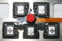
The G, H, B, N, and V key switches all have to be trimmed to accommodate the TrackPoint stick, as shown in the picture to the right. To do so without removing portions of the switch that are critical to its operation, the switches are rotated 90 degrees. It is very likely that these switches will not support spring swapping without complete removal of the switch from the keyboard matrix and mounting plate.
In the case of the B switch, it needs to be trimmed to the extent that its ability to grip the mounting plate is compromised, and must leverage the TrackPoint stick for support.
Super glue was also applied to the switch housing to bond the top and bottom parts together, as the clips on one side were removed.
In future designs, PCB-mounting could be useful for better supporting these keys.
TrackPoint LEDs
Mouse buttons
LED status indicators
RGB LEDs
leg bending, switch mods
LED controller
Teensy++ 2.0
The keyboard uses a Teensy++ 2.0 USB Development Board as the keyboard controller. It has a small enough footprint to fit under the space bar, plus enough I/O pins to support the keyboard matrix and additional hardware components. There are 4 unused I/O pins to spare, unless the OLED display's SD-card reader is to be connected, which requires one additional pin for its chip-select.
Reset button
It is very helpful to have an externally-accessible reset button for the Teensy.
If you ever have a bad flash, it will allow you to force the Teensy into its bootloader so that you can recover without having to disassemble the keyboard.
In the current design, this button is placed underneath the space bar to the right of the switch.
Pin assignments
The Teensy is wired to the keyboard matrix and additional hardware components as defined in the following tables. Some of these pin assignments are arbitrary, while others are based on the mapping of Teensy features to I/O pins (e.g., PWM, I2C/TWI, SPI). Note that it is best to avoid using pin D6 for the matrix columns because the Teensy wires its on-board LED to that pin, and it may interfere with the the ability to sense that column correctly with the pin in a high impedance state.
| Pin | Alt. Function | Connection | Pin | Alt. Function | Connection | Pin | Alt. Function | Connection | ||
|---|---|---|---|---|---|---|---|---|---|---|
| A0 | Matrix row 0 | B0 | SPI SS | Display select (CS) | C0 | Matrix column 8 | ||||
| A1 | Matrix row 1 | B1 | SPI CLK | Display clock (SCL) | C1 | Matrix column 9 | ||||
| A2 | Matrix row 2 | B2 | SPI MOSI | Display data (SDA) | C2 | Matrix column 10 | ||||
| A3 | Matrix row 3 | B3 | SPI MISO | No connection | C3 | Matrix column 11 | ||||
| A4 | Matrix row 4 | B4 | OC2A (PWM) | In-key num-lock LED Green | C4 | OC3C (PWM) | In-key scroll-lock LED Red | |||
| A5 | Matrix column 3 | B5 | OC1A (PWM) | In-key num-lock LED Red | C5 | OC3B (PWM) | In-key scroll-lock LED Green | |||
| A6 | Display data/command (DC) | B6 | OC1B (PWM) | In-key num-lock LED Blue | C6 | OC3A (PWM) | In-key scroll-lock LED Blue | |||
| A7 | Display reset (RES) | B7 | OC1C (PWM) | TrackPoint LEDs | C7 | No connection | ||||
| Port A | Port B | Port C | ||||||||
| Pin | Alt. Function | Connection | Pin | Alt. Function | Connection | Pin | Alt. Function | Connection | ||
| D0 | I2C/TWI SCL | LED controller clock (SCL) | E0 | Matrix column 6 | F0 | Matrix column 12 | ||||
| D1 | I2C/TWI SDA | LED controller data (SDA) | E1 | Matrix column 7 | F1 | Matrix column 13 | ||||
| D2 | TrackPoint PS/2 data | F2 | Matrix column 14 | |||||||
| D3 | Matrix column 1 | F3 | Matrix column 15 | |||||||
| D4 | Matrix column 2 | E4 | No connection | F4 | Matrix column 16 | |||||
| D5 | TrackPoint PS/2 clock | E5 | No connection | F5 | Matrix column 17 | |||||
| D6 | Teensy LED | No connection | E6 | Matrix column 0 | F6 | Matrix column 18 | ||||
| D7 | Matrix column 5 | E7 | Matrix column 4 | F7 | No connection | |||||
| Port D | Port E | Port F | ||||||||
| Pin | Alt. Function | Connection | Pin | Alt. Function | Connection | Pin | Alt. Function | Connection | ||
| +5V | Vcc for SSII controller, LED controller, and OLED display | RST (bot) | External reset switch | AREF | No connection | |||||
| GND (mid) | Ground for SSII controller, LED controller, and OLED display | GND (bot) | External reset switch | ALE | No connection | |||||
| GND (end) | TrackPoint LED ground | VCC (bot) | No connection | Others | ||||||
| Power | Bottom | |||||||||
USB port
External plug
Internal connection to Teensy
Display
Errata
Parts list
| Name | Part No. | Quantity | Purpose | Placement | Sources |
|---|---|---|---|---|---|
| Aluminum case with steel bottom plate | N-A | 6 layers | House components | N-A | [1] |
| Cherry MX switches | MX1A-xx | 22 (A1/white), 32 (F1/green), 21 (E1/blue), 1 (31/lock) | Key switches | Mounted on top plate | [2] |
| Springs | Part No. | Quantity | Purpose | Placement | Sources |
| Key caps | SPH | 76 | On MX switches | Round 4 | |
| Diodes | 1N4148 | 76 | Enable NKRO | Switch matrix | [3], [4] |
| Costar stabilizers | Part No. | 5 sets | Note: The layout used requires a stabilizer for a 7-unit wide space bar. | Under backspace, enter, shift and space keys. | [5] |
| IBM SpaceSaver II keyboard | 28L3644, 37L0888 | 1 | Parts source for TrackPoint IV controller, stick and button assembly. | Controller mounted to case bottom under arrow cluster. Stick mounted onto top plate. Button assembly mounted to internal layer. | Ebay |
| Adafruit 16-Channel 12-bit I2C PWM/Servo Driver | PCA9685 | 1 | LED controller. The Teensy doesn't have enough I/O pins to control all of the RGB LEDs. This controller uses only 2 of the Teensy's I/O pins and can drive 16 LED channels. | Mounted to case bottom | [6] |
| 2x5x5 RGB LED, common anode, diffused lens | LBT25R2G3B2W-ESB-CA | 7 | Indicator LEDs for caps lock, num lock, scroll lock, and config mode. | Four mounted in top plate between escape cluster and main keyboard block, 3 mounted in caps/num/scroll lock key switches. | [7] |
| Teensy++ 2.0 | AVR AT90USB1286 | 1 | Keyboard controller | Inside case under space bar | [8] |
| SPI - 1.5" Color OLED display | SSD1351 | 1 | Display keyboard status and configuration interface. | Mounted through lower-left corner of top plate | [9] |
| Micro-USB breakout board | JS-1579 | 1 | Connector to USB host | Rear of case between main keyboard block and home/end cluster | [10] |
| USB Mini-B Connector | 1389 | 1 | Connect Micro-USB breakout board to Teensy | Rear of case between main keyboard block and home/end cluster | [11] |
| Momentary push button | JS-8879 | 4 | 3 mouse buttons and Teensy reset button | Mouse buttons under TrackPoint button assembly, Teensy reset button under space bar. | [12] |
| Fasteners | Part No. | Quantity | Purpose | Placement | Sources |
| Vinyl film | 1 ft.2 | Insulate components from case | Under all components mounted to the case bottom | Local art supply store |
Software
TMK firmware
Forked version of TMK firmware. Most work currently being done on the develop branch.
