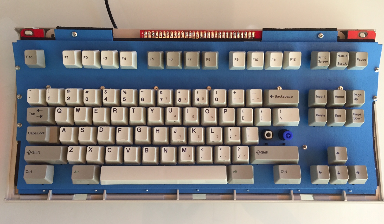
(Model MF) Remodeling the Model M (aka.. the Mara)

User avatar
lot_lizard

20 May 2016, 18:00

The GOAL...

Produce a full DROP-IN REPLACEMENT for the model M by retooling all the inner workings into a completely replicated F (while keeping the key layout of the M).

This means that we could leave our existing M assemblies intact (no modification or bolt-modding), and literally open the outer shell, pull the existing assembly with attached controller out, and drop-in the new unit. Seal the shell back up, plug-in the USB (no adapter), and go.

This has all been made possible by the work i$ did to create a capactive PCB for the model M (code named FSSK/FEXT), which replaces the existing membrane. For that project, we have been able to use F flippers/springs inside our M barrel frame with minimal changes.

This workshop is extending the journey to further the experience towards the REAL objective (a true model F switch with a model M key layout and form factor)... At least it's my "Holy Grail" :)

We originally 3D printed all of these designs to validate the approach, and proceeded through a series of metal prototypes with minor adjustments to finally arrive at a quality product for both the SSK and full-size (101-key). We have had multiple contributors along the way (WCass, Phosphorglow, Techno Trousers, and obviously i$) that have made all of this possible.

If you decide to read through the thread from scratch (good luck), there will be a mention of Phase 1 and 2:
  • Phase 1 is the drop-in replacement for the Model M inner assembly that turns a Model M into a functional F. The only parts remaining from the original M are the outer shell (case), and the keycaps.
  • Phase 2 is to be determined, but we would be making a new and unique board from scratch using a new buckling spring switch (hopefully improved) that would support modern layouts, keycaps, case designs, etc.
These two phases are intermixed in this thread because Phase 2 is really an extension of Phase 1. Phase 2 (new board) is really my end goal, but Phase 1 is a baby-step (though a giant baby) towards proving we are capable of doing this. We are using this thread as a "think tank" because the ideas are so closely related.

Phase 1 will be sold as a "kit" (ala-carte in case there are portions of the kit you don't need) for both the SSK and full-size M:
  • Steel assembly top plate powder coated (with a stainless steel limited edition) that accepts either XT or AT style F barrels in a standard Model M layout. Powder coat colors will be black, industrial SSK blue, green, orange, red, and yellow. There is only one version of the plate that includes additional cut-outs for OPTIONAL keys, where unused keys can be capped to prevent debris):
    • winkeys - between Ctrl and Alt on either side of the spacebar
    • Split spacebar - using a right shift, "Code" key from a Wheelwriter, and a Ctrl/Alt key, the spacebar can be split into 3 keys (two 2.25u and one 1.5u)
  • Steel assembly backplate offered in yellow chromate and powder coat (with a stainless steel limited edition)
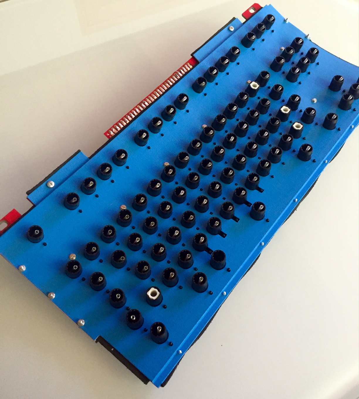
  • PCB derived from i$'s FSSK/FEXT project with only minor changes to allow for optional keys and solderless "slip-on" controller. The PCB will be offered in green/white (SSK)/black (full-size) color options
  • mini xWhatsit Controller modified by WCass using a solderless connection that will be offered in green or black. The controller leverages a daughter USB board for case exit that will be offered in USB-B, USB-C, USB-micro, and USB-mini female port connection options
  • USB port retainer clip that holds the daughter board in place and covers the empty space left by the SDL connector
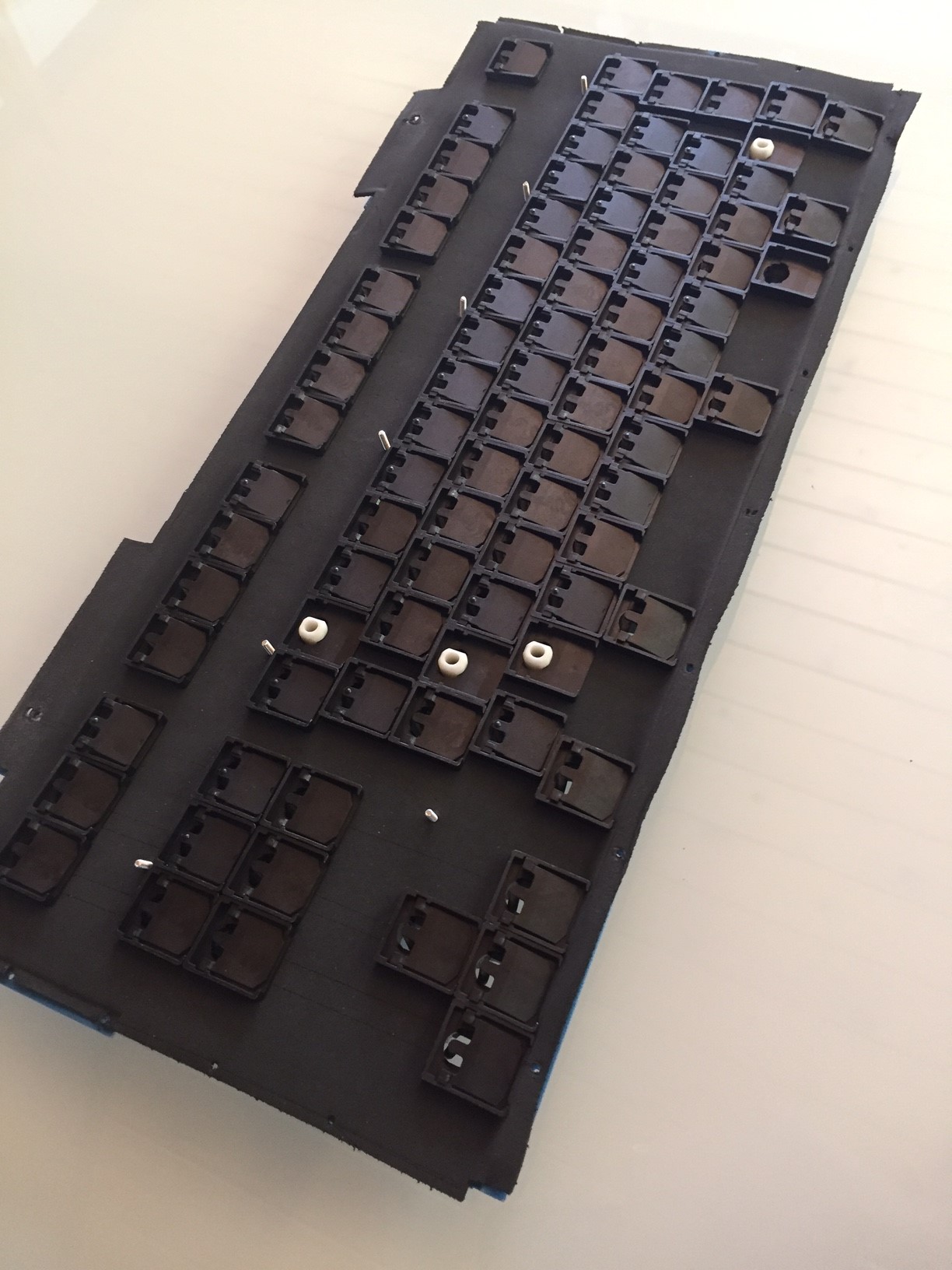
  • "Foam" layer that has been redesigned to both stabilize the keys, eliminate unwanted audible feedback, and better seal the assembly from debris
  • Stabilizer clips with an updated design to cradle wire stabilizers on both horizontal and vertical keys throughout the board (where needed)
  • Fasteners for bonding the plates and sealing the assembly, with o-rings provided in areas that would be tension sensitive like the middle of the board
  • Switches (includes the spring, flipper, and barrel) will not be produced in Phase 1, but so far we have managed to salvage enough switches with Cindy's help to supply approximately 50 boards. It is the one limited commodity of the GB.
Between Phase 1 and Phase 2, we will offer a mini-GB for metal cases. It is unknown yet what these cases will look like in the end, but expect something similar to the stock M shell. We have also discussed LED under-key lighting using the "Phosphorglow" method, and we have opted to add them as an underlay that sits on top of the top plate vs. integrating directly into the assembly (if they are ever produced).

When the GB for Phase 1 commences, it will be a separate Marketplace thread (I'll make sure to post it here for awareness). I expect the GB to run for around a month (or longer if the salvaged switches aren't spoken for). We might open the doors up to GeekHack at the end once the switches are gone.

Everything below are portions of the original post here showing the original plastic printed parts and CAD renderings to produce everything. We have made significant progress since then, but keeping here for posterity. See the first 5 posts in this thread for a fully captured history of events with updates.
________________________________________________________________________________________________

Enough yik-yak, time for photos :). I have used a bunch of spoilers to keep this initial post from being ridiculously long.

CAD renderings for everything (so far). Most have been printed, and confirmed working
assembly.png
assembly.png (136.69 KiB) Viewed 94569 times
  • Top Plate
    Spoiler:
    Model M SSK 84-key top plate adapted to use F barrels from XT/Bigfoot (temporarily since I had on hand).  The stabilizer cutouts will make more sense as you continue
    Model M SSK 84-key top plate adapted to use F barrels from XT/Bigfoot (temporarily since I had on hand). The stabilizer cutouts will make more sense as you continue
    topPlate.png (208.78 KiB) Viewed 94208 times
    Top plate from above
    Top plate from above
    topPlateTop.png (130.12 KiB) Viewed 94208 times
    Top plate side view.  The radial bend is 285mm, when matched with the bottom plate 300mm radial bend, the resulting assembly is ~295mm (matching the M)
    Top plate side view. The radial bend is 285mm, when matched with the bottom plate 300mm radial bend, the resulting assembly is ~295mm (matching the M)
    topPlateSide.png (9.61 KiB) Viewed 94569 times
  • Back Plate
    Spoiler:
    Bottom Plate from below with counter-sunk M2 screws.  The new approach uses screws vs compression tabs like the F (which I have never liked)
    Bottom Plate from below with counter-sunk M2 screws. The new approach uses screws vs compression tabs like the F (which I have never liked)
    bottomPlate.png (21.35 KiB) Viewed 94208 times
  • Assembly
    Spoiler:
    Assembly with spacing added for visualization.  On the sides are spacers to help solidify the construction since there was space in the SSK shell for them, and bonding a radial arc is best done on the curved portions of the cylinder
    Assembly with spacing added for visualization. On the sides are spacers to help solidify the construction since there was space in the SSK shell for them, and bonding a radial arc is best done on the curved portions of the cylinder
    assemblySpaced.png (92.51 KiB) Viewed 94569 times
    Assembly spaced from the side
    Assembly spaced from the side
    assemblySpacedSide.png (12.37 KiB) Viewed 94569 times
    Assembly merged with barrels test fitted.  The gap between the top and bottom plate represents the PCB.  Also, we talked about minimizing the form factor of the assembly.  Notice the gap at the top of the assembly between the plate and the top row of barrels.  If the PCB allows it, all of that could be regained
    Assembly merged with barrels test fitted. The gap between the top and bottom plate represents the PCB. Also, we talked about minimizing the form factor of the assembly. Notice the gap at the top of the assembly between the plate and the top row of barrels. If the PCB allows it, all of that could be regained
    assemblySide.png (20.63 KiB) Viewed 94569 times
    Top with barrels inserted
    Top with barrels inserted
    assemblyTop.png (20.29 KiB) Viewed 94569 times
    Back side of the top plate with all barrels fitted
    Back side of the top plate with all barrels fitted
    assemblyBottom.png (14.9 KiB) Viewed 94569 times
    Close up of the barrel fitting
    Close up of the barrel fitting
    assemblyBottomBarrels.png (104.6 KiB) Viewed 94569 times
  • Barrel
    Spoiler:
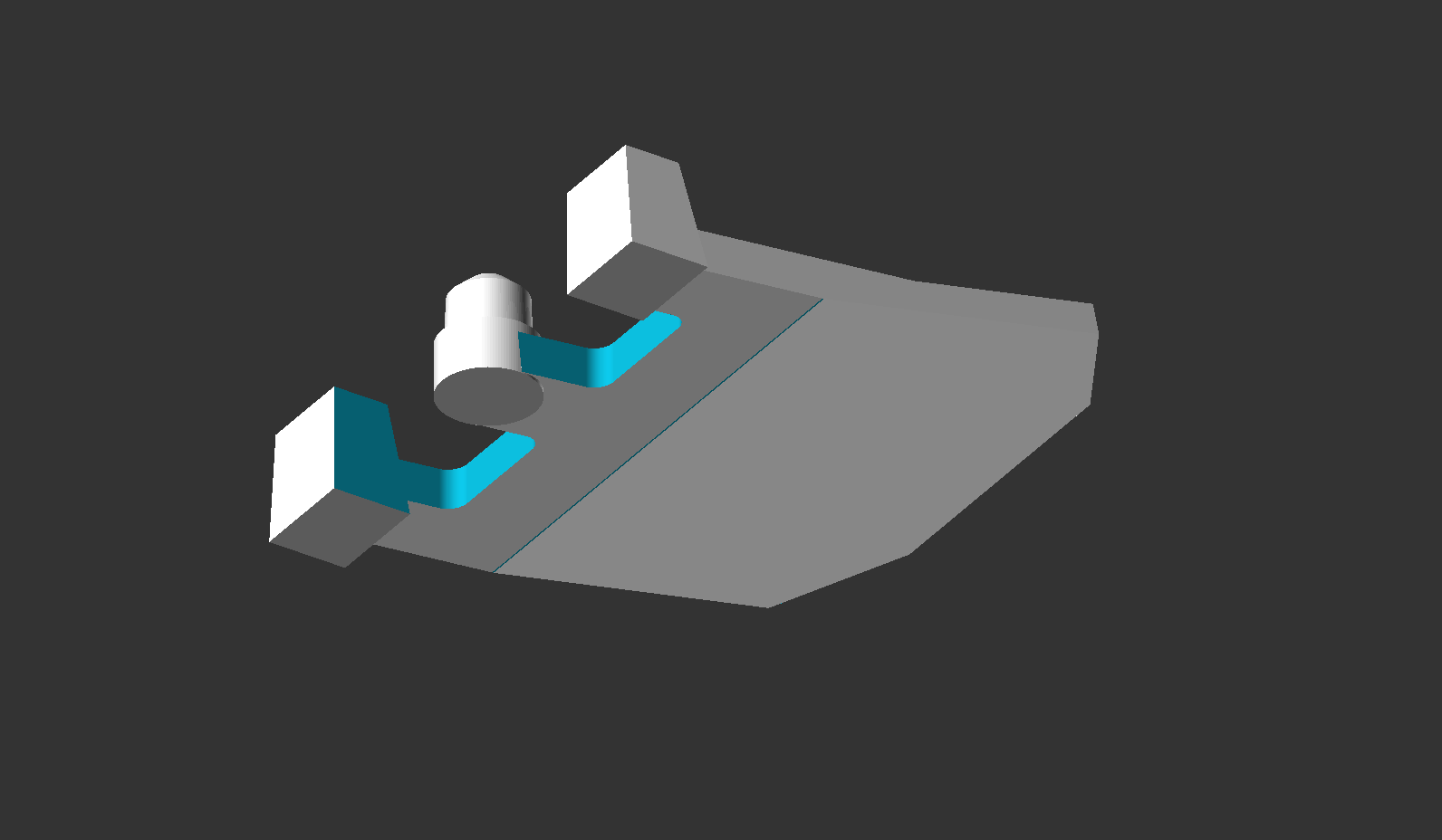
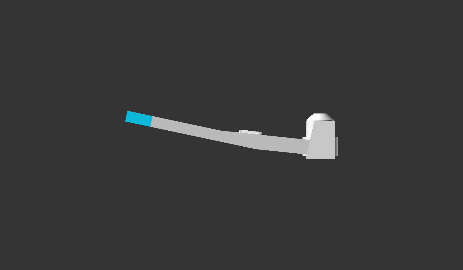
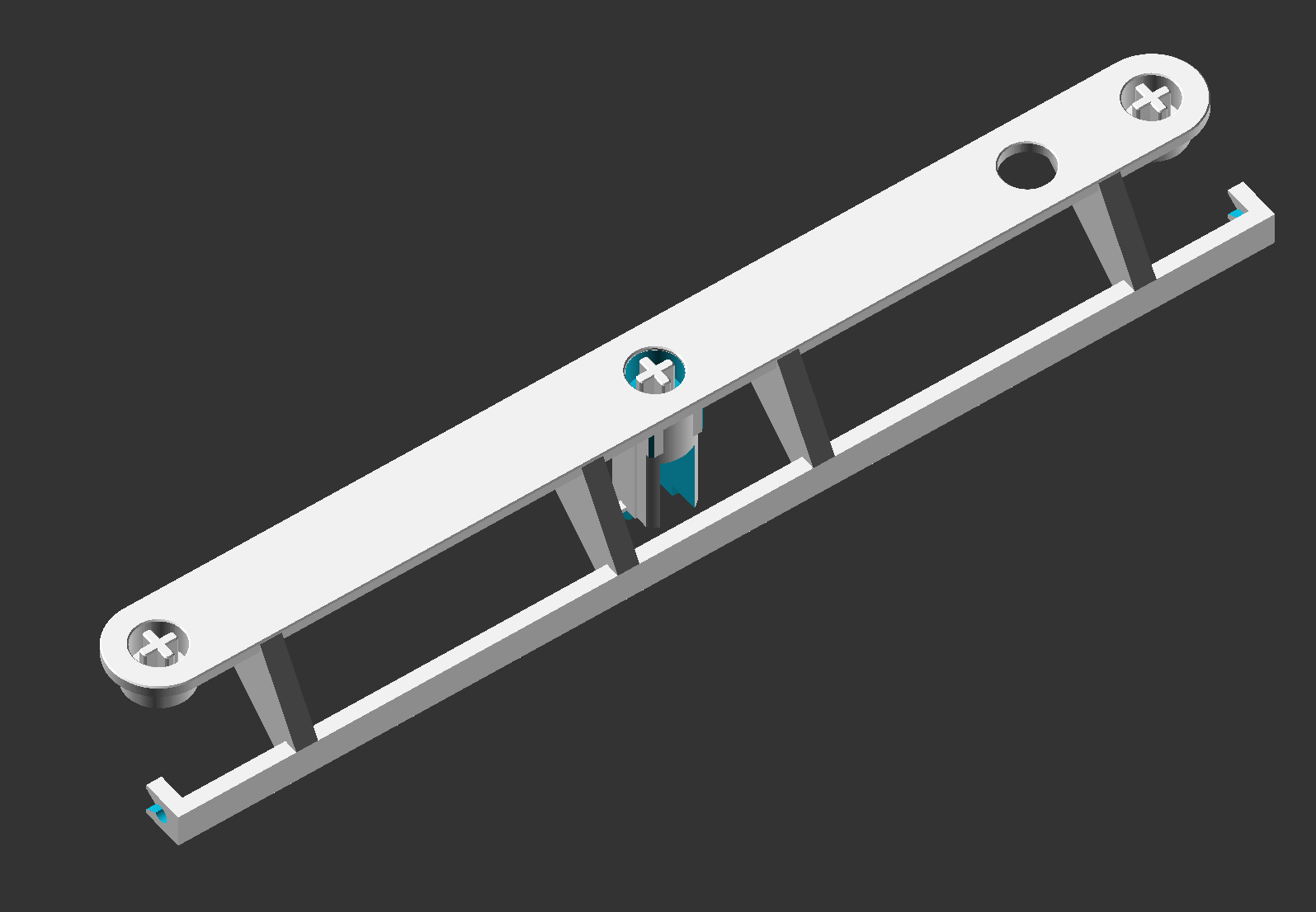
    Barrel with spacebar stabilizer integrated.  This seemed like the most elegant solution (avoiding any spot welding in the manufacturing process, and allowing "easy" replacement should the need ever arise).  The clip itself has substantially more girth than the M or F stabilizer clips
    Barrel with spacebar stabilizer integrated. This seemed like the most elegant solution (avoiding any spot welding in the manufacturing process, and allowing "easy" replacement should the need ever arise). The clip itself has substantially more girth than the M or F stabilizer clips
    barrelClip.png (17.41 KiB) Viewed 94569 times
    ImageAn example rendering of just the cutouts and stabilizer clip barrels
    Standard XT/Bigfoot barrel
    Standard XT/Bigfoot barrel
    barrel.png (13.59 KiB) Viewed 94569 times
    Barrel Bottom
    Barrel Bottom
    barrel-bottom.png (20.21 KiB) Viewed 94569 times
  • Flipper
    Spoiler:
    The real flipper doesn't have the DT logo, but added for fun at the moment
    The real flipper doesn't have the DT logo, but added for fun at the moment
    flipper.png (32.64 KiB) Viewed 94569 times
    ImageFlipper bottom
    ImageSide view of the flipper to note the two step angles
More to come... I am being yelled at on the initial post for number of attachments

Photos of the Printed (functional) Prototype
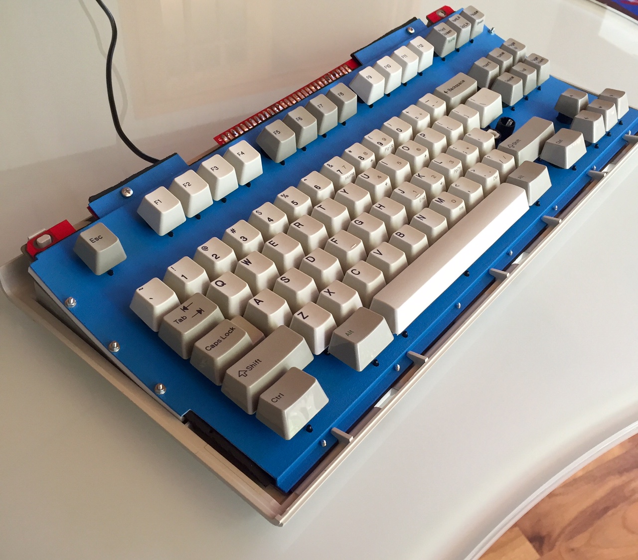
Image
  • Printed Parts
    Spoiler:
    ImageThe plastic parts were from Shapeways, and the little tube is the foam from PhosphorglowImageAssembly front plateImageAssembly back plate with side spacers. Note these would later be cut down to fit the SSK shell (it was difficult to gauge that ahead of timeImageFoam... THANKS AGAIN MAXX

    Shapeways strong and flexible takes paint nicely, and thought it would help visualize the stacked plates, so I put one coat on with a high volume low pressure paint gun. I will let you take a guess at what the SSK case the final version will go into at some point ;)... The colors were color matched a couple of weeks agoImagePainted top plateImagePainted back plate
  • Assembly
    Spoiler:
    ImageAssembly test fitted in the outer shell of the DisplayWrite SSKImageClearance of the barrel peg from a Bigfoot on the bottom row (the one part that I actually was worried about). Worked nicely...ImageFlippers, stabilizers, and additional screws added to the design since this plastic was so flimsy (I can easily fold each plate in half before assembly)ImageAssembled unit with i$'s PCBImage
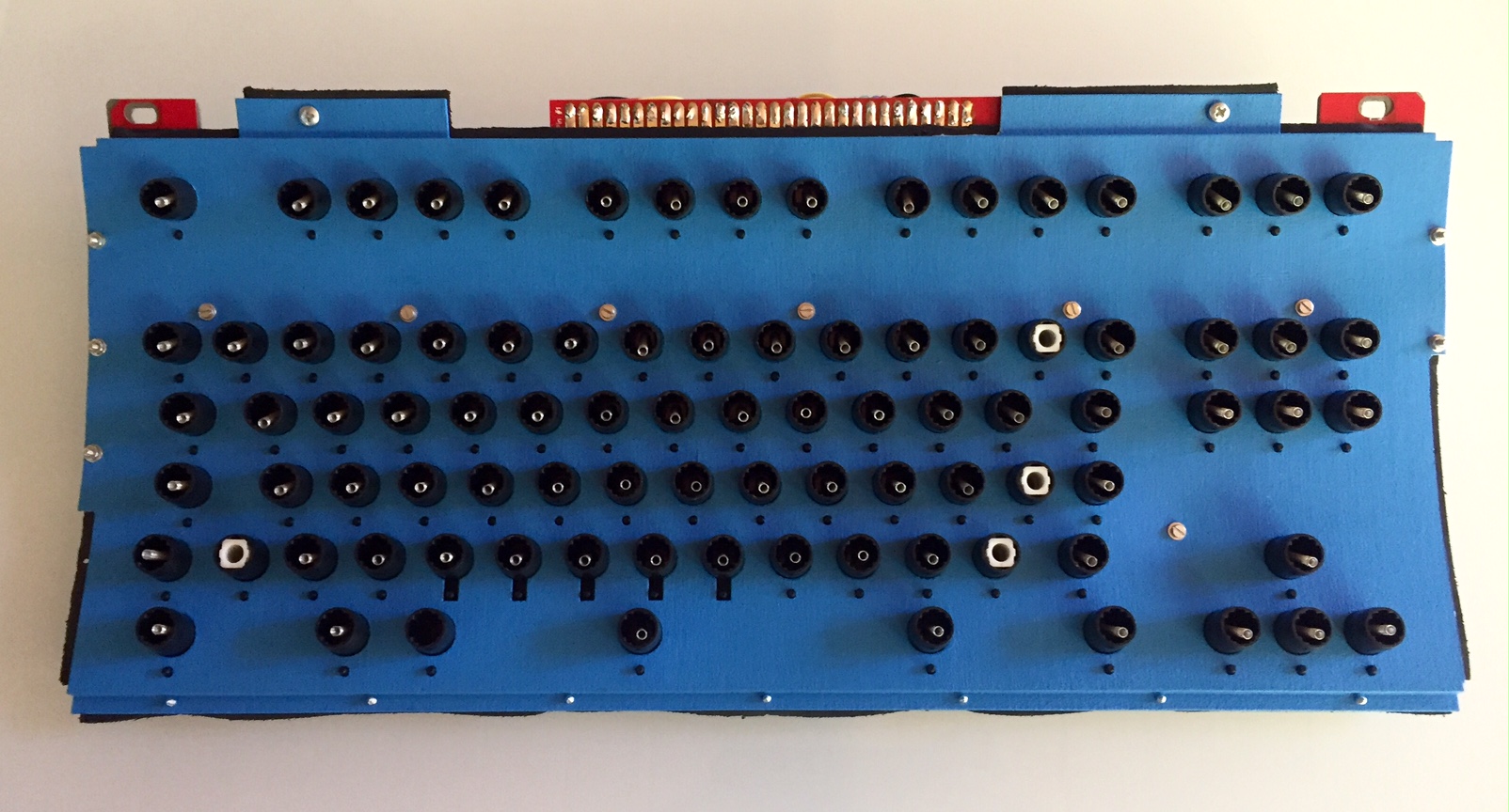
  • Result
    Spoiler:
    ImageThe fully functional prototype with single piece caps borrowed from a 1397681. The little odd "blue key" as Enter/Return is the initial Cherry MX adapter I had printed a while ago. There for nostalagia, and a reminder of what is coming :)
All in all... I am very pleased, and excited about the possibilities going forward. Again, I will keep updating these first few OP's as the project progresses
Last edited by lot_lizard on 08 Jan 2019, 18:26, edited 48 times in total.

User avatar
lot_lizard

20 May 2016, 18:00

Again, the first step in all of this is getting the drop-in replacement working for both the 84 and 101-key M's, but am using this thread as part of a bunch of stuff we might like to do as part of the larger project (unless there are objections thinking it will make it messy).

The following is the original rendering for the Cherry MX buckling spring adapter. I had originally put some of this in matt3o's buckling spring with a cherry on top thread, but would like to just keep track of the progress here, since I view it as another step in this larger goal. Apologies to those that have already seen.
keystemVertical.PNG
keystemVertical.PNG (95.94 KiB) Viewed 93989 times
More renderings of the same stem from different angles
Spoiler:
Backside laying flat on the desk
keystem.PNG (113.94 KiB) Viewed 93989 times
Inside the buckling spring stem from the bottom
keystemBottom.PNG (142.5 KiB) Viewed 93989 times
Cross Section to help visualize the mechanics
keystemCrossSection.PNG (146.98 KiB) Viewed 93989 times
The above would account for all the standard keys, but there are 5 special keys (Spacebar, Capslock, Shift(s), etc) on the 84 key M, and 2 additional on the 101-key. I have ordered a Cherry board to take some measurements from (ironically I don't currently own a single Cherry key :) ), and will progress forward when that arrives.

But using the dimensions of the spacebar from our wiki, have constructed the spacebar adapter (by far the most complex) ahead of time. I am confident it will be very close, but will likely add a sleeve to take advantage of the spare barrel blank on the M (testing will tell for sure)

Image

More renderings of the same stem from different angles
Spoiler:
ImageFront looking upwardImageFront looking downwardImageProfile (the wire clips are there, but not rendered well by the visual)
We discussed a potentially making the plates flat as part of this longer term project (after the drop-in replacement portion is complete), and have NO IDEA if that is even feasible yet without testing... but even if it doesn't, the following is a set of renderings that were put together to show what the Signature Plastics key profiles would be on the curved plane of the M. Looks promising... The blue outline shows the model M/F cap profile as it exists today

Image

And the following shows the progression of how this cap profile "simulation" was constructed
Spoiler:
This is the original:
Image

This is the original in relation to the IBM barrel assembly curve (300mm radial bend for the angle):
Image

And this is the result of the two merged:
Image

This would be the actual rotation of the backplate as it sits in the case. It is possible that Cherry boards sit on an incline in the case as well. I have no idea... don't own one:
Image

And lastly, with IBM keycap profiles in Blue:
Image
I currently have a working prototype for the standard key that I have been using for a few of weeks now, but have sent off for another print with VERY slight changes to the actuation point. The order is FINALLY scheduled to ship from Shapeways on 5/26 (3+ week delay on Acrylate), and I will take detailed pics (possible video) then.

EDIT: Flat plate testing!!!

Disclaimer
I can tell you that before you read any of this, there are two obvious things that would need to occur to make the flat plate version OPTIMAL
  • Barrels reduced - The barrel would need to be shortened on the Y-axis (assuming you are sitting in front of the keyboard, and the width is the X) by ~.5mm per barrel, and the rows would need to be tightened to reflect that change. By flattening the plate, we are increasing the space in between the rows since the keys sit closer to the origin of the radial bend than does the backplate. The great part, the barrels can lose a full ~1mm from the front (~.5mm from the back) before the flipper would need to be altered in any way. This change needs to happen, and should to be in our original barrel order (even for the drop-in since it impacts nothing) as it prepares us for the future, and we continue to have a single barrel mold (flat or curved plate)
  • Flipper pitch flattened - It also stands to reason that the pitch of the flipper should be flattened to contact the PCB pad more evenly. Having said that, I first tested the PCB flat before ever bending, and all keys easily registered. More testing will need to occur here before it is worth declaring a need, but a flipper that is in between the two ending pitches is probably ideal (again... one flipper to rule them all, regardless of plate radius)
Again... enough yik-yak... time for photos
Cold Rolled Steel A366/1008 0.048 inch (~1.25mm) (18 gauge).  I planned on priming and painting, so I selected a higher carbon steel than stainless to provide higher "strength"
Cold Rolled Steel A366/1008 0.048 inch (~1.25mm) (18 gauge). I planned on priming and painting, so I selected a higher carbon steel than stainless to provide higher "strength"
FullSizeRender (27).jpg (508.77 KiB) Viewed 93972 times
  • Bare Plates Received from Big Big Saw
    Spoiler:
    Top plate only, preconditioned (no sanding or deburring)
    Top plate only, preconditioned (no sanding or deburring)
    FullSizeRender (18).jpg (416.03 KiB) Viewed 93972 times
    What big boys use to countersink and deburr circular holes.  With a press, it makes short even work
    What big boys use to countersink and deburr circular holes. With a press, it makes short even work
    FullSizeRender (19).jpg (222.9 KiB) Viewed 93972 times
  • Plates primed with a metal etching primer (to allow for handling)
    Spoiler:
    Top plate primed with a HVLP paint gun after processing (sanding and countersink)
    Top plate primed with a HVLP paint gun after processing (sanding and countersink)
    FullSizeRender (20).jpg (354.03 KiB) Viewed 93972 times
    Bottom plate primed
    Bottom plate primed
    FullSizeRender (21).jpg (297.22 KiB) Viewed 93972 times
  • Foam, Barrels, Flippers added
    Spoiler:
    Foam, barrels, flippers, and stabilizers in place
    Foam, barrels, flippers, and stabilizers in place
    FullSizeRender (23).jpg (332.52 KiB) Viewed 93972 times
    FullSizeRender (24).jpg
    FullSizeRender (24).jpg (339.89 KiB) Viewed 93972 times
  • Compression of the plates with keys added
    Spoiler:
    Everything in place with clamp compression (note...  4 points of compression is WEAK compared to what our end result would be)
    Everything in place with clamp compression (note... 4 points of compression is WEAK compared to what our end result would be)
    FullSizeRender (26).jpg (430.12 KiB) Viewed 93972 times
    FullSizeRender (27).jpg
    FullSizeRender (27).jpg (508.77 KiB) Viewed 93972 times
    Previously mentioned gap that would need to be lessened by ~.5mm per row
    Previously mentioned gap that would need to be lessened by ~.5mm per row
    FullSizeRender (28).jpg (359.37 KiB) Viewed 93972 times
I don't currently have the PCB soldered to the controller yet to prove functionality, but aside from the ~.5mm row gap, this compressed contraption is incredible. The keys feel phenomenal with zero noticeable plate flex, even the keys in the middle make the same consistent "ping". I think I can confidently say at this point (knowing that the flipper test worked on the flat PCB before I bent it... with every key registering perfectly...) this would work if it is desirable for Cherry adapters later. Any additional noise or plate flex (I notice none, and I type HARD) can EASILY be accounted for with additional metal gauge or pressed seams (like the Beamspring). I have zero question this works (assuming the flippers register, and I would be willing play Vegas on that one if someone feels lucky ;)). I am SUPER excited about the doors this testing has opened

EDIT: The Shapeways order including the Acrylate keystem adapters, space bar adapter (the reason the whole order was postponed), flippers, barrels, and barrel stabilizers will be shipped out tomorrow (6/1). I should have an update some time this weekend after returning from my work trip
Last edited by lot_lizard on 31 May 2016, 20:35, edited 7 times in total.

User avatar
lot_lizard

20 May 2016, 18:01

FEXT Assembly Plates

We now have a case for the full size 101-key (FEXT). The only thing open ended here that I see will be the existing LEDs for caps/scroll/num locks, and their integration with the xWhatsit controller headers (especially for the membrane style ribbon cable). To keep the top plate as strong as possible (and eliminate any audible variance for the keys on the top right of the board), the LED location has been made into a cutout vs cutaway. I have left 5mm of clearance on all sides to allow for anything we might need to do with the LED wiring. Also, there were several adjustments as compared to the SSK assembly:
  • The tab cutout that holds the top of the right side of the bottom plate in the lower outer shell was moved closer to the edge (was surprised about this one)
  • Since the full-size M has more room at the top of the outer shell, there is no need for cutaways at the top of both plates to allow the shells screws to pass by (more metal the better)
  • The spacer on the left side of the assembly needed to be reduced to match the right side for case tolerance
  • An additional screw was added at the top of the plates (similar to the ground screw) in the middle for additional support. We could certainly have MANY screws here if we wanted, but I would prefer to have to drill through the PCB as little as possible since there are no cutouts there for screws
I will send this top plate off to Big Blue Saw for water jetting today, and then process the metal for both the FSSK and FEXT. We should have something to report in a couple of weeks

CAD Renderings
Top plate with barrels
topPlateBarrels.png (136.94 KiB) Viewed 93957 times
Additional renderings
Spoiler:
Top plate only
Top plate only
topPlate.png (74.04 KiB) Viewed 93957 times
Top plate from above
topPlateTop.png (22.54 KiB) Viewed 93957 times
Top plate bottom with barrels test fit
topPlateBarrelsBottom.png (177.9 KiB) Viewed 93957 times
Barrel fitting up close for the 10-key portion
topPlateBarrelsBottomClose.png (174.96 KiB) Viewed 93957 times
Bottom plate from above
bottomPlate.png (9.39 KiB) Viewed 93957 times
Assembly with spacing for visualization of the layers
assemblySpaced.png (83.56 KiB) Viewed 93957 times
Spaced assembly from the side
assemblySpacedSide.png (10.8 KiB) Viewed 93957 times
EDIT: I just noticed the renderings didn't include the top-plate cutouts at the upper corners for allowing the pegs from the lower portion of the shell to slip through. This change was made before ordering the water jet cutout, but after the higher-res rendering. It is a very expensive process on the PC to generate these renders on curved planes with test-fit barrels, so I will leave as-is, but noting the change in case someone is evaluating this in real detail
topPlateTop.png
topPlateTop.png (22.77 KiB) Viewed 93915 times
Also, I am not going to be able to brake the offsets on the top and bottom of the top plate using a metal hand brake (what I have), because the ~4mm offset is just too tight for the brake plates I have (by literally 1mm). When I return from my work trip next week, I will have my machine shop friends use a press brake with appropriate die. Should produce a cleaner bend anyway than my artistic version. Video below showing a press brake in action. The 300mm radial curve has been rolled into the FSSK version already, and looks quite nice
https://www.youtube.com/watch?v=j9wdotHTtZQ
Last edited by lot_lizard on 30 May 2016, 19:34, edited 5 times in total.

User avatar
lot_lizard

20 May 2016, 18:01

The Initial Metal SSK Test...

I am happy to report that after a few hours of processing the metal, we have some success to report on the SSK metal prototype front. I am currently typing this from the board, and am for the most part very pleased. I uncovered a small number of issues that are minor, but will mention later after the pics. Again, it is good news, I just report pessimistically :)

What makes up this current build
  • Metal top plate (18 gauge carbon steel... too thin) that has been cut with nitrogen gas for both AT and XT barrels, and bent at ~275mm radial bend. All holes in the top plate are tapped for 2mm screws. Ground screw "taped" off before painting in case it is needed later (so far not the case)
  • Metal back plate (20 gauge... what both should have been... also nitrogen cut) at a 300mm radial bend. The M2 screws in the bottom plate were counter sunk for a tight profile. As with the top plate, the ground screw fender washer was masked.
  • Foam is a neoprene die cut that Phosphorglow was nice enough to send me. It is a bit on the dense and thin side for a production run for later, and is VERY clingy (there is some type of adhesive in the material when compressed).
  • Barrels/flippers/springs are stock from IBM out of an IBM Bigfoot and AT
  • i$ PCB for the FSSK project
  • xWhatsit F controller with a crude ribbon cable. I have managed to procure some .156 pitch cabling from work (don't tell) as a sample, and will use it on the final prototype later (if needed)
  • Fasteners are provided by Fastenal, and I am EXCEPTIONALLY happy with the end result of m2 screws around the bottom and side perimeters, with m3 on the top of the board. I used double sided washers on the top (everywhere else we tapped), with fender washers for the ground screw location if needed.
PIcs...
IMG_7605[1].JPG
IMG_7605[1].JPG (2.11 MiB) Viewed 93544 times
  • Raw metal after tapping and counter sinking
    Spoiler:
    Top plate with m2 taps on all holes except the top
    Top plate with m2 taps on all holes except the top
    IMG_7507[1].JPG (2.3 MiB) Viewed 93544 times
    Backplate countersunk
    Backplate countersunk
    IMG_7511[1].JPG (1.95 MiB) Viewed 93544 times
    Note the differences in radial bend between the top and bottom plates.  This is what adds extra pressure to the center key rows.  It took multiple attempts to get this right
    Note the differences in radial bend between the top and bottom plates. This is what adds extra pressure to the center key rows. It took multiple attempts to get this right
    IMG_7514[1].JPG (1.61 MiB) Viewed 93544 times
    Ground screw taped off for the fender washers in case needed later
    Ground screw taped off for the fender washers in case needed later
    IMG_7516[1].JPG (1.91 MiB) Viewed 93544 times
  • Plates primed
    Spoiler:
    Top plate with self etching zinc primer
    Top plate with self etching zinc primer
    IMG_7520[1].JPG (1.46 MiB) Viewed 93544 times
    Back plate
    Back plate
    IMG_7524[1].JPG (1.17 MiB) Viewed 93544 times
    Backplate countersinks
    Backplate countersinks
    IMG_7526[1].JPG (1.09 MiB) Viewed 93544 times
  • Plates painted and beginning of assembly
    Spoiler:
    Top plate painted (this is by hand because my HVLP paint gun is on loan to a friend
    Top plate painted (this is by hand because my HVLP paint gun is on loan to a friend
    IMG_7552[1].JPG (1.49 MiB) Viewed 93544 times
    Top plate barrel fitting
    Top plate barrel fitting
    IMG_7553[1].JPG (1.39 MiB) Viewed 93544 times
    Top plate barrel fitting back
    Top plate barrel fitting back
    IMG_7575[1].JPG (1.32 MiB) Viewed 93544 times
    Flippers added...  ready to assemble
    Flippers added... ready to assemble
    IMG_7580[1].JPG (1.97 MiB) Viewed 93544 times
  • Assembled
    Spoiler:
    Fender washer for ground screw
    Fender washer for ground screw
    IMG_7582[1].JPG (1.74 MiB) Viewed 93544 times
    Countersunk m2 screws with spacers (had significant impact)
    Countersunk m2 screws with spacers (had significant impact)
    IMG_7585[1].JPG (1.8 MiB) Viewed 93544 times
    Bottom row with spacebar ready to go for XT barrels
    Bottom row with spacebar ready to go for XT barrels
    IMG_7588[1].JPG (1.74 MiB) Viewed 93544 times
    Column alignment (running out of images for a single post, but both sides are identical)
    Column alignment (running out of images for a single post, but both sides are identical)
    IMG_7601[1].JPG (1.67 MiB) Viewed 93544 times
    Happily peacocking its winkeys
    Happily peacocking its winkeys
    IMG_7605[2].JPG (2.11 MiB) Viewed 93544 times
  • It's new home. Time to unveil why I like the floating case concept for phase 2
    Spoiler:
    Where I work from when not traveling.  Love it
    Where I work from when not traveling. Love it
    IMG_7630[1].JPG (1.6 MiB) Viewed 93544 times
    Nestled by a glass of celebration...  It's goodness
    Nestled by a glass of celebration... It's goodness
    IMG_7634[1].JPG (1.83 MiB) Viewed 93544 times
Lessons learned, and corrections in the works
  • Not sure what I was thinking exactly, but the 4704/AT barrel lock was noticeable off. I am correcting the ~5 degree rotation
  • The F key row was off by ~.5mm from desirable. This has been corrected for both the SSK and 101-key.
  • The plates when processed from the machine shop were both curved at a ~300mm radial bend. I spent substantial time getting a smaller even radial bend on the top plate (smaller radial = more curved). There wasn't enough pressure from the top plate to hold the middle rows well. The lower bend radius accomplished this nicely (eventually)
  • The spacers (white plastic holding the plates on the edges is HUGE. Way more necessary than I originally anticipated. Functionally everything was fine, but the pitch was off on the edges. A firm adhesion with the spacer solved an issues on the edges, and will be better in phase 2 when we can have a full length spacer. Having one in phase 1 would require changes to the PCB from i$ (a big deal)
  • The pitch on the middle of the F key rows is off. Again, they work and feel fine (not noticeable with headphones), but F5-8 is slightly more muted. The thicker metal top plate would help with this, but I will proceed with other avenues in the mean time.
  • The spacebar stabilizer barrel should hold the stabilizer spring about 1mm higher to be optimal. This change has been made
All and all... extremely happy with the result. We strive for perfection, so we will try to finish tuning the slight sound discrepancies along the way.
Last edited by lot_lizard on 05 Jul 2016, 21:12, edited 3 times in total.

User avatar
lot_lizard

20 May 2016, 18:01

Adding a few placeholders per i$ suggestion

User avatar
ohaimark
Kingpin

20 May 2016, 18:09

Would you consider designing a standard Model M plate as well? We'd obviously need another capacitive PCB design, but it would add a lot of value to regular Ms.

User avatar
lot_lizard

20 May 2016, 18:21

ohaimark wrote: Would you consider designing a standard Model M plate as well?
100% yes.... I should have had that in the post, but got carried away with pics. Thanks for reminding me. That is actually step 2 once the SSK metal version works

User avatar
pyrelink

20 May 2016, 18:27

i$ already has the FEXT so the PCB design is already taken care of for a full sized M.

Just personally I am super stoked for this project lot_lizard. Both yours and i$'s work on this has been incredible, and I can't wait to get one of these in my hands.

One question for you, (not really important, but just to sate my curiosity) do you happen to know the thickness of the neoprene foam that you had Phosphorglow cut for you? Was it 1/16"?

User avatar
emdude
Model M Apologist

20 May 2016, 19:11

I will certainly be watching this project. :D

May I suggest adding additional holes for barrels between the Ctrl/Alts, for Windows/Super keys? I know that most people would not be keen to cutting their case to fit such keys, but since somewhere down the line you want to produce a new, all-metal case I think it would be neat to accommodate that possibility.

User avatar
seebart
Offtopicthority Instigator

20 May 2016, 19:17

I've said it for years now; my dream keyboard is still a Model F in form of a SSK M. Can't wait for this, keep up the great work. ;)

User avatar
need

20 May 2016, 19:32

What are the differences between a F and M barrel plate?

User avatar
ramnes
ПБТ НАВСЕГДА

20 May 2016, 19:45

Wow, this is awesome lot_lizard!

I'm sooooo in for a metal SSK...

User avatar
lot_lizard

20 May 2016, 20:13

need wrote: What are the differences between a F and M barrel plate?
The M barrel frame is actually a single piece of molded plastic that contains all of the barrels while acting as the top plate. The barrel pattern itself is actually identical (why the FSSK project has worked so well). The F has a metal plate with cutouts for each independent barrel, with foam to help dampen and isolate resonance between the barrels. I will post a study I have done with literally every combination of spring, PCB, barrel, and flipper between the M and F (I tried every combination I could think of... it's A LOT of combinations).

The two factors that really make the F experience so much more "crisp" are the flipper surface area on contact, and the isolated barrels (even more so than the foam). The next biggest factor is the quality of the plastic of the F barrels themselves and lack of friction they have on the keystem. Even a simple gouge test of the two plastics is very revealing.

User avatar
esoomenona

20 May 2016, 20:21

This is great work, and I'm glad I saw it. I had no idea about the FSSK project, so thanks for enlightening me. I've long felt that the form factor and design of the SSK outweighed the slightly better feel of a Model F, thus opted for the former over the latter, but to know that work is being made to have the best of both worlds, well that's just swell. I look forward to seeing this come to fruition for all. Good job!

User avatar
need

20 May 2016, 20:25

Thanks for the clarification, this is so exciting!

User avatar
idollar
i$

20 May 2016, 20:34

Well done lot_lizard !!!
Lets see how the community can contribute to this project.
You can count with me. This is the spirit !

User avatar
lot_lizard

20 May 2016, 20:39

pyrelink wrote: One question for you, (not really important, but just to sate my curiosity) do you happen to know the thickness of the neoprene foam that you had Phosphorglow cut for you? Was it 1/16"?
I should have measured... Apologize for that. 1/16" (~1.5mm) would be very close before compression based on handling. Since I knew it was temporary, I didn't pay too close of attention. The important part that it helped me with was knowing that the "flattened" version of the top plate was true. I was then able to take that and send off to have the metal top plate cut with a water-jet (used Big Blue Saw for the prototype, and should have back in a couple of weeks).

It will come back flat, and I am actually planning on experimenting with the flat plate a bit first before I roll (curve), break (bend), and tap the screws myself. The bend to the plates add substantial rigidity, but I would like to know how much of that is really perceivable. The reason I even point it out, if the plate can be close to "as effective" (perceptibly) in flat form, we can further stiffen with increased thickness or press ridges like the beam spring plates. Then the Cherry MX key idea REALLY has amazing merit. As it currently stands, the pitches of SA/DSA would be altered by the plate pitch, but not severely. NOTE: this wouldn't be something to even consider for the drop-in replacements at the moment... only if we decided to make our own cases (but I would still like to know for later).

The following was something put together to show what the pitches of the various Cherry MX profiles from SP would be on a 295-300mm curved plane. The blue outline are standard IBM keycaps. I was very pleased with the potential
Image

EDIT: I literally just got an email saying the plates were shipped from Blue Mountain Saw. Those guys really are the best if anyone ever has a similar need (I submitted 2 days ago). Even in bulk they are very reasonable for domestic work (10+ quantities, they would have been sub 50 USD a plate). So we will know something next week :)

User avatar
pyrelink

20 May 2016, 22:13

Gotcha, 1/16" is what I used on my other Model Fs, just wanted to confirm. Getting SA keycaps on a Model F would be seriously cool, and if I understand what you are talking about correctly, your idea is to see how well the board holds up when used with a flat plate/PCB, as that would eliminate the profile issues with SA keycaps?

The other thing I am interested in hearing more of your thoughts on is this:

Image

As you know the original setup for Stabilizers kinda sucks for the Model F. They have those really weak popins that can easily break, and you are relying on wires. Usually now you just use the Model M barrel stabilizers for most of the keys, but you still have the issue with the Spacebar. I know Wcass (I think) has that washer method for replacement clips etc.

I know you also have that fancy space age looking render for the spacebar/MX mount adapter. So I was wondering what your thought process is for stabilizers.

EDIT: just took a closer look at the main render again, and see where that barrel fits into the plate. So basically just use these stabilizer barrels for the space bar on the 5th row.

User avatar
lot_lizard

20 May 2016, 22:51

pyrelink wrote: \would eliminate the profile issues with SA keycaps?
Exactly... we would be flat like the Cherry boards, so the profile of the caps would be identical. There are a lot of moving parts here in these special key caps (Capslock, Shift, etc.) and sweet talking i$ into potentially moving the PCB around a bit to make it work (it seems very doable, but needs more study). I would only be interested in the Cherry MX keys if we could do ALL of them. An errand IBM PBT would look ridiculous. Again, I just want to test the flat plate to see how crazy that seems. This thread is about to full of wild ideas (hopefully mostly from you guys fueling it :) ), so be prepared!
pyrelink wrote: just took a closer look at the main render again, and see where that barrel fits into the plate. So basically just use these stabilizer barrels for the space bar on the 5th row
Again... exactly. This one I am very confident in (other than the cost for the tooling for another ABS mold). Even if we have to 3D print 200 of these in HD, the cost will be very reasonable compared to spot welding clips in the assembly process. The other part, metal on metal is never the best idea regardless of friction force unless there is some lube applied on some frequency. This would take us back to the original IBM design of metal on plastic (plastic on plastic everywhere else) for moving parts. The more I study this stuff... these guys (and gals) really were bright, and typically did things back then for reasons other than cost (they were in an era would there was no competition, and the customer would pay). The M introduced cost savings. Plus this design gives us "easy" replacement at some point

User avatar
Chyros

20 May 2016, 23:05

I can never believe how much effort you guys always go through to get smaller keyboards xD .

Well, this looks very impressive, best of luck with the project :) .

User avatar
Muirium
µ

21 May 2016, 03:11

This is immediately one of my favourite projects ever started on DT. Fingers crossed it meets its epic goals!

I'm absolutely up for a drop-in Model F upgrade for the SSK. Got one keyboard that could really use it. Huge win. The only extra magic whisker I can think of to add to the unicorn is Bluetooth. Xwhatsit was interested in doing that as a next step, back when I was prototyping the Model F controller for him. Wonder if we can get him back in the mood again with the fruits of this project…

Adding MX adapters to the mix is completely fruity! I, for one, value the curved IBM backplate very highly. Do you reckon DSA has any chance of working on an adapter equipped (but otherwise still curved) SSK? I could be tempted by SA or indeed Matteo's current work in progress MX/beamspring caps, but going flat backplate is a huge change for a buckling spring board. I'd expect a dazzling new low-profile case to tempt me good and proper. With just enough room round back for a bank of batteries for the you-know-what!

Anyway, Lizard you're a madman, in the best possible way. Let's do this crazy beautiful thing!

User avatar
fohat
Elder Messenger

21 May 2016, 03:32

Muirium wrote:
This is immediately one of my favourite projects ever started on DT.

Adding MX adapters to the mix is completely fruity! I, for one, value the curved IBM backplate very highly.

Lizard you're a madman, in the best possible way.
The only extra magic whisker I can think of to add to the unicorn is Windows/Super/whatever keys.

And don't ditch the full-size because people drool over the SSK.

User avatar
lot_lizard

21 May 2016, 04:04

emdude wrote: May I suggest adding additional holes for barrels between the Ctrl/Alts, for Windows/Super keys?
I know I$ already has spots on the PCB for split left and right shift, as well as ISO enter, but he is missing the ctrl/alt gap keys. I agree we should have one PCB that accomplishes any wants, and a top plate to match. I'll update the CAD for the plates soon to accommodate (won't be in the first metal protoype though). Nice catch
Muirium wrote: The only extra magic whisker I can think of to add to the unicorn is Bluetooth. Xwhatsit was interested in doing that as a next step, back when I was prototyping the Model F controller for him. Wonder if we can get him back in
I would LOVE that too. Time for someone with higher DT "pay grade" than me to do some pleading.... Wink wink ;). The more help the better!!!
Muirium wrote: ...but going flat backplate is a huge change for a buckling spring board. I'd expect a dazzling new low-profile case to tempt me good and proper. With just enough room round back for a bank of batteries for the you-know-what!
Flat plates might be a complete "dumpster fire" of an idea, but I'll be in a unique place to try it... So why not?!? I have purposely left my second FSSK PCB from i$ flat for testing. If it I can get it very comparable (I'll try thicker back plates, different foam, etc), it would definitely open up options for us from caps to cases (at least we will know going forward).
Chyros wrote: I can never believe how much effort you guys always go through to get smaller keyboards xD
Just to be clear, getting a replacement F in the M (84 and 101 key) is step 1. With everyone's help, WE WILL make that happen. I am just throwing out the other things I would like to be cognizant of along our journey. I don't think we have any plans initially of trying to reduce the size, but if we are making something from scratch, let's make it as small as possible (the inner parts), so we can reduce the form factor later if we want to. I would be perfectly happy with all the goals (even a subset) I mentioned in the original post in the same model M form factor. To me it is already the most attractive and useful (workhorse) board on earth. The inside just needs some tweaks to be like it's predecessors. I would like to use this thread as the "Model M Playground" going forward

User avatar
Khers

21 May 2016, 10:00

Imressive progress, lot_lizard! I am really looking forward to the finished FSSK sandwich to drop into my SSK case!

User avatar
Spaceman1200

21 May 2016, 13:45

Wow, so much Model F and M love as of late, any chance of a full size version as well?

User avatar
lot_lizard

21 May 2016, 15:23

Spaceman1200 wrote: ...any chance of a full size version as well?
fohat wrote: And don't ditch the full-size because people drool over the SSK
Promise :). The 101-key is loved (especially during tax season, etc). As pyrelink said, i$ is already in the process of testing the PCB for the full size M (it is designed, produced, and in his possession. We will update the plate designs as soon as he feels comfortable proceeding

Also... I added quite a bit regarding the Cherry MX adapter to the 2nd post
workshop-f7/remodeling-the-model-m-t13796.html#p308666

User avatar
esoomenona

21 May 2016, 15:53

fohat wrote:
Muirium wrote:
This is immediately one of my favourite projects ever started on DT.

Adding MX adapters to the mix is completely fruity! I, for one, value the curved IBM backplate very highly.

Lizard you're a madman, in the best possible way.
The only extra magic whisker I can think of to add to the unicorn is Windows/Super/whatever keys.

And don't ditch the full-size because people drool over the SSK.
Hey, fohat. Long time no talk. I think using Ctrl in place of caps opens up two extra keys on the bottom row to be used for Super keys. I've done this on my SSK via keytweak to emulate the HHKB layout. I know if I had this project in had, I'd want to put it in my SSK case, and wouldn't want to start chopping it up for extra keys.

Though, I will say, if people are open to that, adding the ability to add some extra 1x keys in between the original Ctrl and Alts is a super idea. I'm always open to having extra possibilities.

User avatar
Muirium
µ

21 May 2016, 16:08

Tada.

No, it's not something I want to do to my SSK.
But yes, it's a nice option to have. Especially for future custom cases.

User avatar
photekq
Cherry Picker

21 May 2016, 16:51

Awesome work. Looking forward to seeing more.

User avatar
idollar
i$

21 May 2016, 17:40

Spaceman1200 wrote: Wow, so much Model F and M love as of late, any chance of a full size version as well?
@Spaceman and all other interested: I have a working FEXT (full size M working with F PCB/xwhatsit/PCB) prototype without any problem !!!

As it should be, I am typing this post with the first of the FEXT, based on the PCB v1.00b with the XMIT keys (which I have not tested as I do not feel like breaking the case that I have)

I will post this in various threads in which this PCB is discussed.

Post Reply

Return to “Workshop”